By Dave Harrold
An increasing number of companies are finding that carefully considering the human factor in operator interface and control room designs is contributing significantly to productivity and operational effectiveness.
What sets these companies and their control rooms apart from the control rooms most of us are familiar with is that only the people who need to be in them are there, and every aspect of these control rooms has been carefully considered to ensure that the operator maintains high levels of vigilance and situation awareness.
These control rooms are not the place where maintenance stops by to get a stale donut and cup of coffee; not the place where contractors line up to get hot-work permits; not the place where people drop off order forms for their kids cookie, candy bar and trash bag sales; not the place where people congregate and talk about last nights ball game. No, these control rooms exist for one thing and one thing onlyto operate the plant as efficiently and productively as possible. These control rooms are the operators equivalent of an air-traffic control center, and until you embrace that mindset, your plant will never achieve its full operational excellence potential.
Defining the Workplace
Be it poorly designed graphics, alarm overload or poor control room layout, there are numerous documented cases that validate that when human factors and ergonomics (fitting the workplace to the worker) are left out of design considerations, operators are frequently and unnecessarily distracted, often resulting in needless injuries, equipment damage, off-spec product and so forth. Eventually someone realizes that plant operations are performing less than optimally, and a costly retrofit project is initiated. But will the project produce the desired results?
Worsley Alumina Pty Ltd., Worsley, Western Australia, is among the growing list of companies that are realizing that fitting the workplace to the worker is key to achieving operational effectiveness.
Arnold Oliver, Worsleys superintendent of process control, says, We believe much of Worsleys success is the result of our engaging competent consultants and fully embracing a situation-awareness initiative that incorporated people, alarms, graphics, training and control room design. As a result of our attention to detail, our control room operators are now better informed and thus are making better decisions in less time.
The process Worsley described is a relatively new design concept known as human systems integration (HSI), and it is being effectively used by the U.S. Department of Defense and the National Aeronautics and Space Administration in the design of military battlefield and space travel systems. HSI incorporates a disciplined, unified and interactive approach to integrate human considerations (both cognitive and physical) into a design to improve total system performance and reduce injuries and costs of ownership. HSI incorporates manpower, personnel, training, safety and occupational health, survivability, habitability and human factors engineering.
Integral to the HSI process is applying human factors engineering/ergonomics (HFEE) to fit the work to the worker, instead of forcing the worker to adapt to existing working conditions.
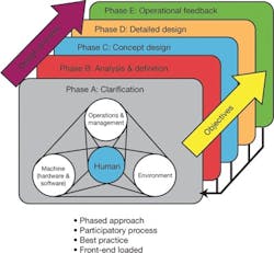
Figure 1. ISO 11064 ergonomic design standards
One of the most vivid examples of a need to consider HFEE is in the control rooms of many process plants worldwide.
How often do you see a press release, brochure or magazine article celebrating a successful start-up that includes a photo of an operator sitting at the operator console? Most likely, the photo showed a bunch of monitors and keyboards plopped down on some computer furniture. What you didnt see was that the control room was built like a box, and then someone was tasked with fitting all the people, equipment, supplies and kitchen into it.
Operators need to be allowed to do what they are trained and paid to do and that requires that they be provided an environment that is void of as many unnecessary distractions and disruptions as possiblesomething akin to an air-traffic control center.
Whats the Goal?
The goal in designing a control room is to create a work environment that promotes the operators ability to maintain high levels of vigilance and situation awareness, says Ian Nimmo, founder and president of User Centered Design Services, and who one client describes as the godfather of situation awareness and alarm management.
Through the late 1970s, control rooms consisted of long panel boards with logically grouped recorders, controllers, indicators, switches, lights and alarm light boxes arranged to provide operators with a big picture of the process.
Beginning in the 1980s, the introduction of distributed control systems (DCS) shrunk those long panel boards into fifteen-inch monitors. To compensate for the operators loss of the big picture, additional monitors were added, along with lots and lots of DCS-based alarms. It was not uncommon for a process plant to evolve from 150 alarm light boxes to more than 2,000 DCS-based alarms.
The distributed architecture of the DCS also encouraged control room consolidation, thus replacing face-to-face conversations between the control room and field operator with sometimes less-than-reliable radio communication. Greater physical distance also changed how supervisors interacted with the control room and field operators. Combined, these changes resulted in the creation of an entirely different control room environment, and it was done with very little thought about its impact on operational performance. Whats truly sobering is that twenty-plus years later, many of those same problems continue to exist in control rooms worldwide.
Planning for the Worker
The ISO 11064 standard, Ergonomic Design of Control Centers, form an excellent foundation for control room design and address such topics as specifying ergonomic principles, recommendations and requirements; control room and adjoining room arrangements; control room layout; workstation recommendations and design guidelines; environmental considerations and much more.
ISO 11064 becomes most beneficial when supplemented with additional process-industry-related guidelines, such as EEMUAs 191 guidelines document, Alarm Systems: Guide to Design, Management and Procurement; its 201 guideline document, Process Plant Control Desks Utilizing Human-Computer Interfaces: A Guide to Design, Operational and Human Interface Issues; Electric Power Research Institutes (EPRI) Alarm Management and Annunciator Applications Guidelines; and best practices from organizations such as the Abnormal Situation Management (ASM) Consortium.
Assembling such a library of standards, guidelines and practices is one thing; feeling comfortable in interpreting and appropriately applying them is something quite different. When in doubt, seek council.
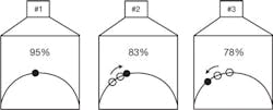
Figure 2. One of Acuites simple yet intuitive means of indicating furnace performance is shown here. Similar techniques can be implemented in most of todays operator interface workstations.
Some companies incorrectly decide they want the control room to have a certain look and feel without really understanding the operators needs or how the control room and field operators work during various operational phases (i.e., start-up, normal, abnormal, critical, shutdown, etc.). A control rooms design should be based on improving operational performance, not a design for the sake of being different, counsels Nimmo.
Control rooms designed per ISO 11064 generally end up with either a theater or functional style, however within each of these basic styles, there are numerous variations. Depending on the operators needs, one style is likely a better solution than the other, but until interviews are conducted, people are observed on the job, the interaction of operators is understood and unit and process complexities and interactions are collected, it is impossible to say which style and variation is best for a given installation.
Shrinking Head Count, Bigger Control Room?
The process industries shrinking knowledge base, caused by the retirement of older workers with their wealth of institutional knowledge, is old news at this point. Some companies are addressing this problem by combining local unit control rooms into a centralized control room. Their rationale is that fewer operators will be required, and the close proximity of operators will help disseminate process knowledge and enhance collaboration among plant units.
To the casual observer that seems to make sense, but as Peter Yacoe, plant manager at Calgon Carbon Corp.s Big Sandy plant in Catlettsburg, Ky., points out, Ian [Nimmo] and his team provided valuable insight to Calgon Carbon in developing practical options and solutions to our control room consolidation efforts.
Useful Graphics
Because of its broad industry coverage the ISO 11064 standard does not address alarm and graphic designs. For that, documents such as EEMUA 191 and 201 and ASM Consortiums Effective Operator Display Graphics guideline become beneficial.
Simplicity is the basic rule of thumb here.
Lisa Garrison of Acuite, a company with extensive expertise in operator graphic designs says, When it comes to designing useful process control graphics, we need to forget that we have 256 colors available; we need to forget what weve seen in video games and what we see on TV during an automobile race. The goal of every process control graphic should be to provide the operator readily usable information and near-instant recognition of abnormalities.
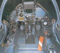
Ever looked inside the cockpit of a modern jet fighter? You will see lots of analog gauges clustered together by function. The grouping and placement are the result of understanding the pilots (operators) needs. Now take a look at the graphics your operators are using. Were they designed with functionality in mind, or do they mimic the P&IDs?
Most operators, especially experienced ones say P&ID-like graphics exist for the benefit of engineers and plant managers. They admit that such graphics arent that useful to them.
A senior operator at a major plastics manufacturer summoned it up nicely when she said, We already know what the plant looks like, and we know exactly where things are located. Besides, a bunch of digital values up and down a multi-colored and highly detailed graphic arent much use to us because no one bothered to include a simple reference point.
The message is loud and clear: Every control room operators ability to remain vigilant and rapidly respond to abnormal situations is the direct result of his or her working environment and how much needed information is presented to them.
Graphic Analysis
Acuites Nick Dinadis suggests evaluating existing operator graphics using the following criteria:
Content: Operators can only be effective if the operator interface provides them with the right information at the right time in a usable and logical manner. Often graphics are designed for normal operation and dont support abnormal situations, such as start-up or shutdown. Documenting the different graphics and keystrokes/point-and-clicks required during different operational phases can provide valuable insight into what graphic modifications are warranted.
Format: Even the best information is of little help to operators if it is not communicated as efficiently and reliably as possible. Everything from the appearance of meters and equipment to the use of colors and text must be consistently tailored for optimum usability. Recommendations include the use of a gray-scale color palette; reserving specific colorsi.e, yellow and redfor alarms; use of deviation bars; the use of advanced analytical graphics, such as multi-point spider webs (polar stars) driven by thirty to forty data points; and other intuitive health-at-a glance graphic elements.
Structure: The types and organization of graphic pages is critical to overall operator effectiveness. Based on industry- acknowledged best practices, the consistent organization of a multi-tiered graphics hierarchy is an important first step to providing operators with usable information and near-instant recognition of abnormalities. For example, Level 1 = overviews; Level 2 = task-oriented, major system overview and primary operating graphics; Level 3 = additional detail, similar to todays graphics; and Level 4 = non-control and help displays.
Processes, quality and production demands, and automation systems have changed dramatically during the past twenty years, so doesnt it make sense that control rooms designs should also change?
If air-traffic controllers require a well-designed, functional environment in order to maintain high levels of vigilance and situation awareness, why is it so difficult to think that process control operators dont require, in fact deserve, a similar working environment?
Dave Harrold is co-founder of the AFAB Group and a regular Control contributor.
Extra-Credit ReadingHere are some additional resources to help you get started on your control room redesign. |
Defining Operator Vigilance and Situation Awareness
|
26 Injured1995 Texaco Refinery in Milford Haven, WalesBadly designed HMIs and alarming systems quickly can make a bad situation even worse. Analysis of this 1995 accident revealed the following:
The incident developed from its initial causative problems largely because of the combined effects of two factors. Firstly, operators were not provided with information systems configured to help them identify the root cause of such problems The interface between the operators and the control system should have been designed to give the operators and manager overview facilities through the display. |
Continue Reading

Leaders relevant to this article:


