Modeling the Weather, Measuring Bulk Solids with Radar and Benchmarks for Loop Checking Productivity
This column is moderated by Béla Lipták , automation and safety consultant, who is also the editor of the Instrument and Automation Engineers’ Handbook (IAEH). If you have automation related questions send them to: [email protected]
H. Crowney
[email protected]
A: The past and present measurements of the water and air current flows, temperatures, heats of condensations (enthalpies), salinities, insolations, etc. are mostly available, and based on them, future trends can be estimated. Our data shows that as carbon dioxide emissions increase, the heat received by the East Coast rises. (Today mankind [numbering 7 billion] is yearly sending 35 billion tons of carbon into the air, nearly 5 tons per person. The global population is estimated to rise to 9 billion by 2050 and to 12 billion by 2100, and the per capita energy consumption in the third world is estimated to double. The carbon emission in the future will depend on the rate of conversion to the Post-Oil Energy Economy, http://www.amazon.com/Post-Oil-Energy-Technology-Solar-Hydrogen-Demonstration/dp/1420070258) The heat balance on the East Coast is influenced by the amount of insolation that it directly receives (Qs), by the heat which air and water currents (Qa & Qw) bring from the south, and the cooling caused by the melting of the ice at Greenland (Qi). (For the purposes of simplicity, I am disregarding the heating/cooling effect of the winds from the north and west.)
Using existing data, we can calculate and plot the relationship between the change in total heat input (ΔQt) and the change in CO2 concentration. From that plot, we can approximate the dead time and time constant (gain) of this heat transfer process.
The total heat input (Qt) can be estimated by Equation (1):
Qt = Qs + Qa + Qw – Qi (1)
In Equation (1), insolation (Qs) can be measured directly. On the East Coast it averages about 1200 kWhr/m2.
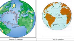
The heat conveyed by the air currents (Qa) move poleward. As evaporation increases near the equator, more heat is carried by the winds and hurricanes, which transport evaporated moisture up the East Coast, where it is released in the form of increased rain. The amount of this heat (Qa) can be measured by detecting the air flow and the heat of condensation of its moisture content.
The heat conveyed by the ocean currents (Qw) can similarly be measured by detecting the flow rates and temperatures of the arriving and returning currents. Making these measurements would also be useful to resolve the debate concerning the slowing of the Gulf Current (Figure 1). Some argue that the Gulf Current is slowing because the melting of the ice at Greenland lowers salinity (density) of the ocean, while others argue that this effect is smaller than the effect of the increased heating at the equator, which increases this flow.
As to the measurement of the rate of the melting of the ice (Qi) at Greenland, it could be detected indirectly by measuring the reduction in salinity of the receiving ocean.
Global warming is a batch process! The rate of warming is slowed by the melting of the ice on Greenland. This ice is the “air conditioner”of the planet, and once it is gone, the rate of temperature rise will increase.
Therefore, if a process control engineer was asked to model this overall heat transfer process, he/she would install sensors to measure the water and air current flows, temperatures, heats of condensations (enthalpies), salinities, insolations, rate of melting of the ice, etc., exactly the same way as we would model any other heat transfer process. Based on the above measurements, one could determine the dynamics of this control loop, including its time constants.It should be emphasized that this is a batch process! In other words, the heat tranfer model would only be correct while there is still ice on Greenland. Once that ice is gone (like the ice in a glass of your gin and tonic at the pool in the summer, which stays cool only until the ice melts), the rate of warming would jump.
Béla Lipták
Q: Solids Level Measurement. I have a question relating to measuring the level of bulk solid using radar. I found the equation shown below for the level measurement of solids for the determination of the true dielectric constant of bulk solid:
True Dc = (Dc of solid - 1.0)(Bulk density/solid density) + 1.0
The Dc of solids is defined in exactly the same way as it is for liquids. However, solids for processing are ground into powders or small granules and contain space between the particles that is filled with gas having a specific gravity of 1.0.
I was looking is several manuals including yours, and couldn’t find the theoretical or empirical support for the above equation. I know that the radar technology has some restriction concerning the dielectric constant (Dc) as the “true” dielectric constant relates to the bulk density, but would like to understand it better.
Francisco Alcalá.
[email protected]
A: For solids level consider sonic technology which also enables you to obtain 3D mapping if the surface is uneven. See http://www2.emersonprocess.com/en-US/brands/rosemount/Level/Solids-Measurement/3D-Solids-Scanners/Pages/index.aspx, for example.
Jonas Berge
[email protected]
A: First of all, the different manufacturers handle the measurement of bulk solids slightly differently, so just using the formula may not be as precise for all cases. Having said that, I see more of an issue with other factors than the actual level measurement.
Having worked with a number of bulk solid storage systems, we have found that issues like temperature, dusts, particulates in suspension in the air, the cone formed inside the storage vessel, etc., have a bigger impact on correct measurement than the dielectric constant.
Also remember that the dielectric constant is correct for only a very narrow range of temperature, so if the product enters hotter or cooler than expected, or if the vessel alters the storage temperature of the solid, all of these will affect the true dielectric constant.
Also the size, shape and symmetry of the solid particles will be varying, since it is very difficult to always produce exactly the same size granule, and size will affect such properties as angle of repose, constants, flowability, etc.
Alejandro Varga
[email protected]
Q: Loop Checking Productivity. What are the industry standard benchmarks for loop checking productivity? I am looking for norms for digital and analog loop checking frequencies in DCS control systems.
Brian Libbey
[email protected]
A: My experience is as follows:
Digital loops : 50-75 in 10 hours;
Analog loops :10-25 in 10 hours.
The above quantity will vary based on how well the continuity has been checked before start of the loop checks, problems encountered during loop checking, communication skills, permits, etc.
H. S. Gambhir
[email protected]
A: The industry direction is smart commissioning. For instance in the case of projects using digital fieldbus, much of the device commissioning tasks can be automated:
Auto-Detection: The fieldbus system automatically detects all fieldbus devices when they are connected, not just transmitters and control valves, but also discrete devices like intelligent on-off valves.
Auto-Identification: The fieldbus system automatically gets the device tag, device unique ID, manufacturer, device type and version, etc. and automatically assigns an address to every device.
Auto-Binding: The fieldbus system automatically binds the device to the control strategy, that is, the physical device gets associated with the placeholder for the device in the system database, and all the I/O signals in the device are associated with the I/O functions in the control strategy. Simple devices have only one I/O signal, but most devices have multiple I/O signals you can use. It is all automatic for all devices, not just some.
Auto-Integration: The fieldbus system automatically selects the corresponding EDDL file for the device in the intelligent device management (IDM) software part of the asset management system (AMS).
Auto-Configuration: The fieldbus system automatically downloads the configuration to the device including units and range if applicable. There is no need to make settings one by one from a handheld. All devices can be configured (customized) for the application, not just transmitters and control valves, but also discrete devices like intelligent on-off valves.
Auto-Checking: The fieldbus system diagnostics automatically checks whether the device communication is good; a digital loop check and continues checking forever, alerting to any installation issue, such as water ingress in device housing.
Auto-Documentation: The fieldbus system automatically lists all devices with card number, port, device tag, commissioning state, manufacturer, model/type, revision, unique ID and address, etc.
Jonas Berge
[email protected]
