Should you use a Coriolis flowmeter as a backup system? Plus a search for information about diaphragm gas meters
This column is moderated by Béla Lipták, automation and safety consultant, who is also the editor of the Instrument and Automation Engineers’ Handbook (IAEH). If you have an automation related question, send them to: [email protected].
Q: Coriolis for orifice backup? I am working at RCSPL, a design and detailed engineering company for the oil & gas sector in India. The conditions of my application are these: Service –fuel gas line; Pipeline size – 2 in.; Flow rate – 1,000 lb/hr.
Presently an orifice meter (concentric square edge) measures the fuel gas flow. The client wants a Coriolis flowmeter in series with and upstream of the orifice plate to provide it with backup. Are there any problems that we should consider concerning this installation? If not, please advise how the installation of this Coriolis flowmeter should be made?
R. Muthuganesan
[email protected]
A1: The Coriolis flowmeter is superior to the orifice-type sensor because it directly measures the mass flow, has low maintenance, requires practically no straight pipe runs and provides both better accuracy and better rangeability than does the orifice-based flowmeter. The orifice is a volumetric flow detector and therefore requires pressure, temperature and density compensation to determine the mass flow, requires more maintenance, longer straight pipe runs, and both its accuracy and rangeability are lower. For these reasons, I would not use the Coriolis meter as a backup, but would use it as the primary sensor.
As to installation, I would prefer to install the Coriolis meter downstream of the orifice, because the Coriolis has practically no upstream straight pipe run requirement while that of the orifice is substantial, particularly if an upstream restriction is present, such as a smaller-than-pipe-size Coriolis meter. In your case, in the 2-in. pipe, the Coriolis will probably be 1 or 1.5 in. Its preferred installation would be in a vertical pipe with upward flow direction (Figure 1). This should be in a location where there is no vibration and the pipe does not transmit much compression, tension or shear force onto the meter.
Finally, I should note that while this addition will provide a backup, still, when the two meters disagree, you will not know which reading is the right one, although the probability is that it will be the Coriolis. You should provide block and bypass valves, so when one meter is removed for any reason, you can continue operation using the other.
Béla Lipták
[email protected]
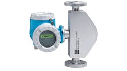
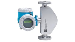
The Coriolis flowmeter is more accurate and reliable than an orifice, therefore it should be the primary sensor and not a backup for the orifice.
Credit: Endress+Hauser
A2: Based on my experience, both types of flowmeters are suited for the described application. There is nothing special in the installation requirements of the Coriolis instrument. The supplier of the instrument will give you any requirements/recommendations, if such exist.
Avihu Hiram
[email protected]
A3: In general you will have difficulty reconciling the measurements between the Coriolis (basically a mass flow device) and the orifice plate. The conversion from mass to volumetric flow on a fuel gas line (gas has low density) will not be accurate due to the density measurement not being accurate for lower densities.
This is also a problematic configuration because there will be discrepancies between the two readings, and the user will have to continually justify them. Also this does not account for any inaccuracies in the orifice reading.
I am not sure that the client understands "backup," since the measurements will disagree, and the client will not know which is to be taken as the good one.
You have not really given enough information about the process. We need to know:
• Gas pressure, temperature and density;
• Allowable pressure drop (you now have additional instrumentation in the line);
• Piping configuration (e.g., is there a pressure regulator in the gas line?);
• Whether this is feeding a fuel gas header or an individual piece of equipment (e.g. fired heater); and
• Reliability requirements.
There are straight-run requirements for an orifice plate (more for upstream). It would be better to place the Coriolis downstream of the orifice because it will introduce significant flow profile disturbance for the orifice. You will need at least a 40-pipe-diameter straight pipe run from the Coriolis if installed upstream of the orifice plate. (You could probably get away with five to 10 diameters if the Coriolis is downstream.)
You can go to the vendor websites and find the sizing procedure for the Coriolis meters. There you will find data on size, required pressure drop, etc.
However this would not be the sort of installation I would do. I would choose one flowmeter or the other, but not both.
Simon Lucchini
[email protected]
A4: Technically there is no problem in putting them in series, provided straight pipe length requirements are adhered to. If you do not have sufficient length, I suggest you can remove the orifice plate and preserve it for use when the Coriolis meter is not working. With this you may be able to satisfy the required straight lengths.
However since the Coriolis meter is more accurate and failures are very few, if possible, you can consider stopping use of the orifice plate permanently.
H. S. Gambhir
[email protected]
A5: The only issue that you need to take into account is the upstream straight pipe distance required for the Coriolis meter and the orifice. From this perspective, one can view the Coriolis meter as a valve or restriction to the flow. By making this assumption, you can use Table 3 of ISO 5167:2 to determine the straight pipe requirement of the orifice meter if the Coriolis is upstream of it. Depending on the beta ratio, the upstream pipe lengths will be between 12 and 24 pipe diameters.
If the beta ratio is between 0.5 and 0.65, the pipe diameter requirements are between 12 and 18. Therefore, in a 2-in. line, the Coriolis meter should be more than 24 in. upstream of the orifice plate and not more than 36 in. If there are more bends and changes of direction, then the required pipe lengths need to be adjusted accordingly.
Alejandro Varga
[email protected]
Q:Diaphragm Gas Meter. I am a retired professor of physics, and I am seeking knowledge related to the good old diaphragm gas meter. I am searching for persons and/or documents with deep engineering knowledge on the strength and weaknesses of a device that was invented 120 years ago.
In the present meters that are still sold, a lot of accumulated engineering know-how was developed along a learning curve stretching on a century. In your Instrument Engineer's Handbook you have one page on the principles. I an searching for more detailed knowledge on the relationships between the meter performance (metrology, flow range, temperature response) and the nature and design of the components (gears, membrane, temperature compensation).
Could you guide me toward references (thesis, engineering notes, review, etc.) or direct me to people you know who are or were active in this field sometime ago?
Jacques Schmitt
[email protected]
A: You will find a fairly good summary of diaphragm type positive displacement flowmeters here. The chief engineers of the suppliers of these meters, which have evolved since 1890, are familiar with their relative merits and can provide you with the information you need.
Béla Lipták
[email protected]


