This column is moderated by Béla Lipták, automation and safety consultant and editor of the Instrument and Automation Engineers' Handbook (IAEH). If you have an automation-related question for this column, write to [email protected].
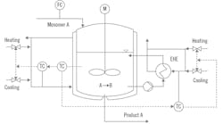
First, does it make sense for the master controller to send the same setpoint for both slave controllers? If it does, are there preconditions, such as "jacket has dominant effect on reactor temperature?” If not, could you please tell me why, and give me some suggestions how to do this?
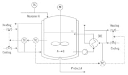
Figure 1: The reactor is currently provided with a jacket and an external heat exchanger (EHE) to control temperature. The cascade master controller controls the reactor temperature and manipulates the setpoints of two slave controllers, one on the jacket, one on the external heat exchanger.
Second, I want to test the design by first feeding the reactor only with water (no reaction). I'm not sure about tuning the slave controllers. If I use step-response tuning, should I apply it from the jacket/heat exchanger inlet temperature to the jacket/exchanger temperature? (The jacket/heat exchanger inlet temperature and jacket/exchanger temperature are not the same; there is heat transfer from jacket to the vessel; and the reactor is connected with the heat exchanger—the material in the reactor can go to the exchanger.) Or, can I directly use a step response from the jacket/heat exchanger inlet temperature to the reactor temperature? Besides that, what should I do to design the master controller?
Zeping
[email protected]
A: The purpose of slave controllers is to correct for the effects of disturbances (i.e., valve sticking, heat transfer media pressure or temperature changes) from upsetting the cascade master. Therefore, the slave controller must always control the outlet temperature of the heat transfer equipment, so their dynamics are included in the slave loop (which should be at least four times faster than the master).
Two slaves with the same setpoint is a bad idea because near the transfer point between cooling and heating, they can easily end up cycling or fighting each other as it's possible for one to be cooling while the other is heating. I would use a single slave and place it on the larger heat transfer unit (jacket).
Also, the two heat transfer units should be arranged in series for being used in sequence. In that configuration, at low loads (heating or cooling), only the jacket should be used, and the external heat exchanger (EHE) should only start supplementing it when the loads are high (exceed the jacket capacity).
As to control modes and tuning, the cascade master controller is usually PID. In this case, I would tune it at both high and low loads, in both the heating and cooling phases of operation. I would switch among these four memorized settings where the transfers occur. I would also program the system, so the switching occurs when the master controller is on setpoint (the error is zero). If the process requires it, I would also provide high and low limits on the temperature setpoint of the slave. The slave control modes are usually proportional-derivative or proportional only, with the proportional band set between 10% and 20%.
The relationship between the slave temperature and the flow of the heat transfer medium (water or steam) is nonlinear, so to compensate for that, we use nonlinear, equal-percent characteristics in the control valves. The failure position of the steam valves is (always) closed (FC), and the failure position of the cooling water valves is (always) open (FO).
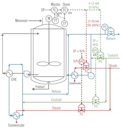
Figure 2: As described in the text, reverse-acting (R/A) controllers provide maximum heating at the slave output of 20 mA, maximum cooling at the slave output of 4 mA, and the transition from heating to cooling near 12 mA. Use valve position controllers (VPC), and when the primary valve opening rises to 90%, start opening the valves to the supplementary heat transfer unit (EHE). Use a back pressure controller (PC) on the water return, and an external reset (ER) to the master controller from the slave measurement.
As shown in Figure 2, both the master and the slave controllers are reverse-acting (R/A), meaning that when their measurement increases, their outputs drop. Maximum heating occurs (red loop in Figure 2) at the slave output of 20 mA (100%); maximum cooling occurs (green loop in Figure 2) at the slave output of 4 mA (0%); and the transition from heating to cooling occurs at 12 mA (50%). Near the transition point, I usually provide a small gap, so the switching between heating and cooling will occur without cycling. This means that instead of switching at exactly 50%, the control algorithm would be switching to heating at, say, 49%, and would be swiching back to cooling at, say, 51%.
In throttling the four valves, one could split the slave output into four segmenets (0-6, 6-12, 12-18 and 18-24 mA), but I found it better to place valve position controllers (VPC) on the primary heating and cooling valves (the ones serving the jacket in Figure 2). And, when the primary valve opening rises to, say, 90%, only then would we start opening the secondary valves serving the supplementary heat transfer unit (EHE).
An important component of the control system in Figure 2 is the back pressure controller (PC) on the water return. This controller is needed to make sure that no water will leave the recirculating water loop during the heat-up cycle because that would cause cavitation.
Another important feature of the control system in Figure 2 is the external reset (ER) to the master controller from the slave measurement. This is needed because without it, when the operator switches to manipulate the slave setpoint manually, the cascade master will be blocked from having access to the slave setpoint, and therefore its integral control mode will wind up (keep integrating the error and eventually saturate). This would result in bumping the system when the operator switches the controls back to automatic.
Béla Lipták
[email protected]
A: The usual reason for slave control loops is to isolate the primary control from short-term changes in jacket temperature, so the designer may have wished to stabilize the inlet to the heat exchanger, For that, the output of the jacket temperature control will go to the third controller that controls the valves. This loop system might also have limits on temperature for safety issues.
Cullen Langford
[email protected]
A: The example is difficult to understand. I don’t see enough temperature elements, thermocouples or RTDs, and it’s not clear what is being cascaded to what. What is the fast inner loop, and what is the outer loop? It appears that this is a dual control problem with heat required at one stage, and cooling required after the reaction begins, but I don’t see the two controllers that would be required. It also appears that the reactor jacket does not supply enough cooling/heating since there is a separate circulation stream for heating and cooling. On the other hand, it is difficult to understand this process from the incomplete P&ID supplied.
Dick Caro
http://dickcaro.blogspot.com
