System overview
This Mimic database is a demonstration of two things: a compressor system with surge that can accurately model real behavior and a prototype control system for the compressor. The primary demonstration of this compressor object is a compressor system that cools and recycles the surge into a header upstream of the compressor (in the node COOL_RECYCLE_100MS_MKII).
The basic compressor supports a single input, with a surge valve attached to the compressor and a downstream plenum to which the throttle valve is attached – this can be found in the node ATM_VENT_100MS_MKII. The demo included in this database adds an upstream header, a heat exchanger, associated valve dynamics for both the surge valve and heat exchanger flow valve, and controls on both valves.
Compressor with surge
The compressor used in these demonstrations was a single-stage centrifugal compressor (a small turbocharger with a vaned radial diffusor) without variable guide vanes. Attached to the compressor directly is a surge valve and a downstream plenum to which the throttle is attached. Based on models by E.M. Greitzer and K.E. Hansen, this compressor system can model both positive and negative flow into and out of the compressor.
Compressor controls
The compressor system is controlled by a simple PI controller, tuned in such a way to allow proportional action to have more influence than suggested by tuning rules over integral action; this is done to minimize the appearance of overshoot. This controller should handle all normal disturbances; however, inducing the system into surge results in the controller attempting to adjust the surge valve position but never opening it with enough speed or magnitude to make the system exit surge. Taking the place of a skilled operator or alternate control system in this demo is an open loop backup system that can detect when the system enters surge, quickly switch the controller into remote output, and begin ramping the surge valve open immediately (holding control for long enough to ensure the system does not immediately regress into surge).
This open loop backup system is represented by two calculation blocks within Mimic. This system verifies that the flow rate into the compressor is to the right of the surge point on a compressor map and that there is no sharp drop in the derivative of flow (a characteristic sign of entering surge). Once surge is verified, the system begins ramping the valve for 10 seconds at a user specified rate from either the current valve position or a user specified minimum, whichever is greater. After at least 10 seconds have passed and no surge is detected, the system will exit open loop backup and return the PI controller to automatic.
MEMI components
The model itself is a DLL with two associated configuration files. The parameters are as follows:
- Integer registers:
- CONFIG_INDEX: (Write)
- The config index allows the user to specify exactly which configuration XMLs they would like to read. The DLL reads XMLs titled: "Compressor_cfg_{INDEX}.xml" and "start_conds_{INDEX}.xml", where index is the number passed to this parameter. For these demos, which just consider one compressor, 0 is passed. If you would like to keep the original demo XMLs and try testing your own, simply make copies of the XMLs with different indexes and update this value to use them.
- ERROR_CODE: (Read)
- A status passed from CompressorCalculations.dll to all the landing models. During a normal system startup, the code is set to -1 for the first 10 scans; this represents “waiting,” allowing the user to adjust the simulation quickly. During normal operation, the error code is set to the model execution rate in milliseconds (so if the model executes every 50ms, an error code of 50 indicates normal behavior). When the code returns 1, there has been a serialization error; if it returns -2, there has been a licensing error. Finally, an error of 999 indicates that execution has failed due to probable numerical instability.
- REVISION_CODE: (Read)
- This parameter simply gives the revision number of the DLL. The latest version at publication of this document is 7.
- CONFIG_INDEX: (Write)
- Floating point registers:
- COMPRESSOR_MASS_FLOW: (Read – lb/min)
- This parameter returns the calculated mass flow rate through the compressor using the conditions at the previous scan.
- PLENUM_PRESSURE_RISE: (Read – PSI)
- This parameter returns the pressure rise calculated from the compressor inlet (suction conditions) to the downstream plenum.
- COMPRESSOR_PRESSURE_RISE: (Read -PSI)
- This parameter returns the pressure rise calculated within the compressor itself.
- THROTTLE_MASS_FLOW: (Read – lb/min)
- This parameter returns the calculated mass flow rate through the throttle valve.
- SURGE_FLOW_MASS: (Read – lb/min)
- This parameter returns the calculated mass flow rate through the surge valve.
- CALCULATION_TIME: (Read - ms)
- This parameter returns the number of milliseconds taken to compute the prior scan of the compressor model.
- THROTLE_PRESSURE_DROP: (Read - PSI)
- This parameter returns the calculated pressure drop across the throttle valve.
- COMPRESSOR_ACFM: (Read - ACFM)
- This parameter returns the current volumetric flow rate into the compressor.
- COMPRESSOR_SPEED: (Write – RPM)
- This parameter allows the compressor’s impeller speed to be adjusted online.
- SURGE_VALVE_DS_PRESS: (Write – PSI)
- This parameter allows for a downstream pressure for the surge valve to be set, such as for an atmospheric vent or connection to any other vessels, piping, or systems.
- SURGE_VALVE_PCT_OPEN: (Write - %)
- This parameter defines the surge valve percentage open, with 1 representing a fully open valve and 0 representing a fully closed valve. This value is modified in all demos by the control system.
- THROTTLE_VALVE_PCT_OPEN: (Write - %)
- This parameter defines the throttle percentage open, with 1 representing a fully open valve and 0 representing a fully closed valve. Unlike the surge valve, this value is directly adjustable by the user.
- DS_THROTTLE_PRESS: (Write - PSI)
- This parameter allows for a downstream pressure for the throttle valve to be set, such as for an atmospheric vent or connection to any other vessels, piping, or systems.
- UPSTREAM_PRESSURE: (Write – PSI)
- This parameter defines the pressure fed into the compressor from upstream of the compressor; this can be a user-defined constant or changed dynamically (such as when including an upstream header).
- SUCTION_DENSITY: (Write – lbm/ft3)
- This parameter defines the density of the process fluid at the compressor inlet. This parameter should be constantly calculated if using an upstream header but can be manually specified otherwise.
- SUCTION_SONIC_VELO: (Write – ft/sec)
- This parameter defines the speed of sound of the process fluid at the compressor inlet.
- THROTTLE_VALVE_K: (Write - dimensionless)
- This parameter defines a capacitive K-value for the throttle valve that can be changed online after 10 scans.
- SURGE_VALVE_K: (Write - dimensionless)
- This parameter defines a capacitive K-value for the surge valve that can be changed online after 10 scans.
Compressor_cfg_0.xml
- This is a required configuration file for the compressor that describes physical parameters of both the compressor and its compressor map. This model uses a non-dimensionalized compressor map.
- None of these values can be changed online, unlike the DLL parameters. The node must be stopped before any changes can be made.
- Parameters:
- cfg.m_da_suct:
- This parameter defines an initial value for the speed of sound in ft/s of the process fluid at the compressor inlet. Once the initial 10 scan startup delay has passed, this value will be supplanted by the DLL’s “SUCTION_SONIC_VELO” parameter.
- cfg.m_dAc:
- This parameter defines the flow area of the compressor in ft2.
- cfg.m_dAt:
- This parameter defines the flow area of the throttle valve in ft2.
- cfg.m_dAs:
- This parameter defines the flow area of the surge valve in ft2.
- cfg.m_dLc:
- This parameter defines the length of the compressor in ft.
- cfg.m_dLp:
- This parameter defines the length of the plenum in ft. This parameter is deprecated but must be defined.
- cfg.m_dLt:
- This parameter defines the length of the throttle valve piping in ft.
- cfg.m_dLs:
- This parameter defines the length of the surge valve piping in ft.
- cfg.m_dRevLag:
- This parameter defines the “time lag in revolutions” of the compressor.
- cfg.m_dImpellerRadius:
- This parameter defines the impeller tip radius in ft.
- cfg.m_dPlenumVol:
- This parameter defines the volume of the downstream plenum in ft3.
- cfg.m_dSuctionDensity:
- This parameter defines an initial value for the density of the process fluid at the compressor inlet in lbm/ft3. Once the initial 10 scan startup delay has passed, this value will be unused in favor of the DLL’s “SUCTION_DENSITY” parameter.
- cfg.m_dNegA0:
- This parameter defines the coefficient for the 0th order term in the compressor map negative branch polynomial.
- cfg.m_dNegA1:
- This parameter defines the coefficient for the 1st order term in the compressor map negative branch polynomial.
- cfg.m_dNegA2:
- This parameter defines the coefficient for the 2nd order term in the compressor map negative branch polynomial.
- cfg.m_dUnmeasuredA0:
- This parameter defines the coefficient for the 0th order term in the compressor map unmeasured branch polynomial.
- cfg.m_dUnmeasuredA1:
- This parameter defines the coefficient for the 1st order term in the compressor map unmeasured branch polynomial.
- cfg.m_dUnmeasuredA2:
- This parameter defines the coefficient for the 2nd order term in the compressor map unmeasured branch polynomial.
- cfg.m_dUnmeasuredA3:
- This parameter defines the coefficient for the 3rd order term in the compressor map unmeasured branch polynomial.
- cfg.m_dStableA0:
- This parameter defines the coefficient for the 0th order term in the compressor map stable branch polynomial.
- cfg.m_dStableA1:
- This parameter defines the coefficient for the 1st order term in the compressor map stable branch polynomial.
- cfg.m_dStableA2:
- This parameter defines the coefficient for the 2nd order term in the compressor map stable branch polynomial.
- cfg.m_dStableA3:
- This parameter defines the coefficient for the 3rd order term in the compressor map stable branch polynomial.
- cfg.m_dStableStart:
- This parameter defines the dimensionless flow rate at and above which the compressor map is considered stable.
- cfg.m_dThrottleValveK:
- This parameter defines an initial value for the throttle valve K-factor. Once the initial 10 scan startup delay has passed, this value will be unused in favor of the DLL’s “THROTTLE_VALVE_K” parameter.
- cfg.m_dSurgeValveK:
- This parameter defines an initial value for the surge valve K-factor. Once the initial 10 scan startup delay has passed, this value will be unused in favor of the DLL’s “SURGE_VALVE_K” parameter.
start_conds_0.xml
- This is a required configuration file for the compressor that describes additional initial conditions for the compressor model. These values are loaded as initialization conditions for the model.
- Parameters:
- Item 1: Initial compressor mass flow (lb/min)
- Item 2: Initial plenum pressure rise (PSI)
- Item 3: Initial compressor pressure rise (PSI)
Compressor with cooling and recycle
Model overview
This model includes an upstream header from the compressor. This header allows for mixing of a user-defined inlet stream and the recycled surge flow before it is drawn into the compressor. To account for the heating of the process fluid after compression, the recycled flow is passed through the tube side of a heat exchanger. The shell flow inlet valve is manipulated to drive the tube outlet temperature towards the upstream header temperature. This demonstration contains seven standard models: two for control, two for valve dynamics (surge valve and heat exchanger shell valve), two for virtual plant modelling (the upstream header temperature and the recycle loop), and one “landing model” where variables can be observed at a glance.
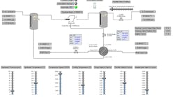
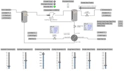
Above is the prototype operator interface; it can be found under Views, titled “RECYCLE_FRONTEND_100_MKII”. This interface allows for quick observation of many variables as well as manipulation of inlet and outlet streams. The only object not adjustable from within the interface is the surge valve PI controller’s faceplate. This is because mode selection is directly set by the open-loop backup and cannot be overridden.
Compressor Control
Most of compressor control is handled within the SURGE_FV_AND_CONTROL model. Control is ultimately handled by two systems: a tuned PI controller that handles small disturbances and an open-loop backup system that, upon detection of surge, will place the PI controller into remote output and quickly begin opening the surge valve until surge is no longer detected. The controller will then return to automatic and adjust the surge valve position on its own. The setpoint to this system sends an uncorrected surge point to the open-loop backup system but a value multiplied by a safety factor to the PI controller. This is to ensure the compressor can operate as close as possible to the surge point to maximize efficiency. This open loop backup is handled by two calculation blocks: IS_SURGE and PREEMP_BKUP.
The control system is more than just reactive. The control system predicts the state of compressor flow two seconds (at 100ms exec time, 20 scans) into the future. This allows the valve to begin stroking before the first surge cycle has impacted the system.
Compressor Views
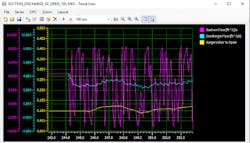
Two useful views are included in the demo database for observing the model’s behavior. Trend View allows the model’s output to be viewed as a trend chart and Component Studio provides a graphical interface for experimentation (as shown and detailed above). The primary Trend View, SUCTION_DISCHARGE_SV_OPEN_100_MKII, displays suction and discharge flows (in ft3/sec) while also displaying the surge valve IVP. Below is an example of the trend with the open loop backup disabled, showing the rapid oscillations in suction flow and the surge valve attempting to correct purely via PI control.
Resource
McMillan, Gregory K., Centrifugal and Axial Compressor Control, Momentum Press, 2010
Continue Reading
Latest from Multivariable Control

Leaders relevant to this article:
