This column is moderated by Béla Lipták, automation and safety consultant and editor of the Instrument and Automation Engineers' Handbook (IAEH). If you have an automation-related question for this column, write to [email protected].
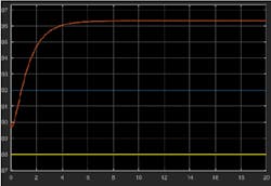
Q: I have question regarding the step response method for PID tuning. I have a chemical production model, and to tune the PID controller, I introduced a step change and obtained the step response curve shown in Figure 1. According to the curve, there was no dead time, so can we still use the well-known Ziegler–Nichols method to do the tuning? And why would this no-dead-time situation happen?
It is a semi-batch process, and one of the control goals is to make sure the reactor temperature stays in a desirable range. To do that, a jacket and external heat exchanger (EHE) are used, and inlet temperature for jacket and EHE are inputs (of course, feed flow rate is also an input). To control the temperature, cascade control strategy is applied. To design the controllers, I applied a step response to the EHE inlet temperature. Before that, I fed only water into the reactor, so no reactions take place. One thing I found very interesting is that a large amplitude has to be applied (about 8,000) to get the s-shaped curve.
Name withheld
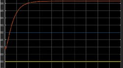
Figure 1: Introducing a step in the simulation of temperature control on a semi-batch reactor resulted in this curve, which shows no dead time. Is it possible to tune it using the Ziegler-Nichols (Z-N) method?
A: In this column, I usually select questions concerning measurement and control problems. This time, the question was selected for a different reason—I want to show the risks involved in using control software without fully understanding it or without being sure that it was developed for your process. In our digital age, when people expect instant answers to everything just by clicking a button, it needs to be emphasized that software is just as good as the person who prepared it and before using it, we must fully understand the process that is to be controlled by it.
To prevent embarrassing the questioner, I have not identified them. After all, he or she is probably a beginner and is doing the right thing by asking questions. Is it the fault of his employer for not checking if they are qualified to handle the task?
That said, the Ziegler-Nichols method of process of tuning was created to tune existing real processes, not models, while the Ziegler-Nichols reaction curve you show has nothing to do with your process, as it is created by a model. This is apparent because there is no such thing as instant response—all processes respond with some dead time (if nothing else, there is always transportation lag). Also, you can’t simulate the dynamics of an exothermic chemical reaction process without having that reaction taking place, because it is the generation of the reaction heat that determines its dynamics.
Therefore, first I will explain what is going on in your semi-batch reactor. Semi-batch means that the process is started with a batch phase of operation and when it is completed, the continuous phase is started. Usually, first a batch of liquid is charged into the reactor. This usually is done under level control, and only after the desired level and the required operating temperature are reached, the continuous phase is started by continuously charging one or more reactants, and sometimes also a catalyst. The reactant is slowly added, and it can be a gas or liquid.
As the reactant is added, the reaction is started, which is usually exothermic. The amount of reaction heat generated is a function of both the rate at which the reactant is charged and the temperature at which the reaction is taking place. Usually, the reaction rate is a function of the operating temperature and therefore, this is a self-accelerating process, meaning that an increase in reaction rate raises the reaction temperature, and that rise in reaction temperature further increases the reaction rate (the heat release). Hence, both the reactant flow and the reaction temperature must be controlled to keep the process stable.
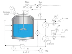
The reaction itself can form a gas, a solid precipitate or in case of hydrophobic reactions, can result in the separation of a mixture of say, oil and water. Figure 2 shows an appropriate control system, but to keep it simple, I left out the flow, level and composition controls, and concentrated only on the temperature controls, because your interest is in tuning the temperature control loops.
For detailed descriptions of reactor controls and of the various methods of PID tuning, please refer to my handbook. As to open-loop tuning of PID loops, refer to my column, „How to determine open-loop gain,” (Control, Nov. ’17, p. 49, www.controlglobal.com/articles/2016/ask-the-experts-how-to-determine-open-loop-gain). Here, I would only say that you have to separately determine the tuning constants for the batch phase (during which heat is being added and reaction heat is not generated) and the continuous phase, during which the reaction heat (Qr) is removed by cooling (Qc).
Naturally, the reactor will be stable only if Qr and Qc are kept equal. Production can only be increased up to the limit of the maximum heat removal capability (Qc)max of the equipment, and if the production rate is likely to be varied, or if the reactor is to be used to handle different reactions, often a feedforward loop must be added. The termination of the continuous phase of operation is based on concentration and conversion detection (x and y), and it triggers a new batch phase of operation, during which the reactor contents are discharged.
Béla Lipták
[email protected]
Figure 2: Here, CW is cooling water, ER is external reset, Fc is coolant flow, FC is fail closed, FO is fail open, Fr is reactant flow, P is positioner, Qc is heat removed by coolant, Qr is reaction heat, RA is reverse acting, SP is setpoint, TCV is temperature control valve, x is product concentration, and y is fractional conversion.
A: It would take quite some time to get into the details of your simulation. However, you can use the Ziegler-Nichols closed-loop ultimate period method—even if you won’t necessarily get the best tuning parameters, you will be able to ballpark some initial values from them.
Secondly, in a real-life application, since this is a batch process, it is recommended to use only the proportional mode (P) in the PID during starting, and only later enable the Integral mode, and even derivative.
Third, don’t get too worried about the lack of dead time. You might be using simulation that is not prepared for mass- or energy-transport delays. Real processes always have dead time, or apparent dead time.
S. Nino, Process control consultant
[email protected]
A: The Ziegler-Nichols method of process tuning was created to tune existing processes, not models. Real processes contain transportation or dead time delays, or multiple small-value time-constants that are equivalent to a dead time delay. Models often lack these details.
Nonetheless, the method can be applied if there are at least two time constants in the model and the steepest slope line of the reaction curve does not intersect the starting point of the reaction curve. This is the case in Figure 1.
Using Figure 1, I find a dead time of 0.15 horizontal units, and a reaction rate or steepest slope of (9 vertical amplitude units) divided by (2.2 horizontal time units). Not revealed in the inquiry is the size of the input step (forcing function) that was applied to get the Figure 1 results.
Knowing the amplitude units, time units and the forcing function units and size, the Ziegler-Nichols controller settings for the model can be computed. The computed controller settings are a good starting point for the real-process controller settings. Because the model does not contain all the time delays of the real process, the gain setting will likely to be found to be too high. Some fine tuning will need to be done on the live process.
Otto Muller-Girard, P.E., FISA
[email protected]


