It is important to understand what the proportional, integral and derivative terms do within the PID controller. That understanding is essential to choose appropriate action, troubleshoot controllers, choose appropriate modifications, or set up advanced controllers. Unfortunately, the controller synthesis approach, in which PID magically appears within Laplace Transform analysis, does not provide that functional understanding. Hopefully, this more intuitive development of PID will be helpful.
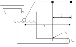
Figure 1: Here, inflow is a variable that will upset the level gauge float, which acts on the lever arm that controls the slide valve on the outflow. The controlled variable, CV, is the liquid level in the tank, h, and the manipulated variable, MV, is the valve stem position, U.
Chosen as an example is a commonly understood process—level control in a tank of liquid (Figure 1). The inflow is a wild variable, or disturbance, that will upset the level, which is an indication of liquid inventory. The slide valve on the outflow will open or close to release more or less fluid to keep the level at the desired setpoint. As notation, the controlled variable, CV, is the liquid level in the tank, h, and the manipulated variable, MV, is the valve stem position, U. Recognize that your region or community may use alternate terminology. The nominal, initial steady state values are h0 and U0.
The controller, also shown in Figure 1, is a mechanical lever, a proportional-only controller. If the liquid level rises somewhat, then the float rises the same amount, which raises the lever that opens the valve an additional amount by the lever proportionality. This releases fluid faster, which seeks to counter the rising liquid inventory. If the liquid level falls somewhat, the lever closes the valve proportionally.
The liquid level may rise or fall for any number of reasons. The inflow rate, Fin, may change, the viscosity of the fluid may change affecting its outflow speed, or the downstream pressure or in-pipe flow restrictions may change, affecting Fout. The reason for a rise or fall in level is immaterial for the controller. This lever action moves the valve in the appropriate direction, and in a manner proportional to the level change.
Proportional action
The lever arm length ratio, b/a, is the gain of the controller. By changing the relative lengths of the lever arms, perhaps by changing the position of the fulcrum, the controller can be more or less aggressive. If the level, h, starts at a base case of h0, which is also the setpoint, hSP, then using simple relations, the equation for the change in the valve stem position with respect to level is:
Where Kc = -(b/a) represents the controller gain and e = (hSP - h) represents the actuating error, the deviation of the CV from its setpoint.
Since ∆U = U - U0, then the equation representing the lever-type control is:
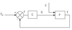
Figure 2: A block diagram of the control scheme in Figure 1 shows the information transfer between controller and process, not material exchange. The block labeled C is the controller, which represents the lever, but could be a calculator that executes Equation (2): it multiplies Kc times e, then adds it to U0.
Figure 2 shows a block diagram of a controlled process using generic symbols for the MV, U; the CV, Y; and the disturbance, d. Contrasting the illustration of the physical process of Figure 1, this represents the path of cause-and-effect information exchange. The controller is shown acting on the actuating error, e.
Note that although termed the process output, Y, the level of the liquid does not come out of the tank. The material liquid goes in or comes out, and level is a measure of the inventory response of the in-tank contents. The block diagram reveals the information transfer between controller and process, not material exchange. The lines in Figure 2 are not pipes. The block labeled C is the controller, which represents the lever, but could be a calculator that executes Equation (2). It is simple arithmetic: the controller multiplies Kc times e, then adds it to U0.
Equation (2) seems very much like what is often presented as a proportional controller, U = Kc e. However, if U = Kc e was the relation, then if the CV were at the setpoint (e = 0), the controller would set U = 0, and close the valve, which would make the level rise, and cause it to deviate from the setpoint. In Equation (2), the term U0 is the controller bias—it's the value of U for which the initial MV position is required to hold the CV at setpoint. As illustrated in Figure 1, this is about 50%.
Figure 3: A block diagram of the P-only control calculation of Equation (2) shows the actuating error is multiplied by the controller gain, and then added to the bias to determine the controller output. These are simple arithmetic operations (not calculus or Laplace-transformed magic).
The user chooses the controller gain. Normally, the controller starts in manual mode (MAN) with the user deciding the MV value, then when the CV is at the setpoint, the user switches the controller to automatic (AUTO) mode. For bumpless transfer, the bias is usually set by the controller as the MV value when the controller is switched from MAN to AUTO.
Figure 3 shows a block diagram of the arithmetic operations in the P-only control logic of Equation (2). The actuating error is multiplied by the controller gain, and then added to the bias to determine the controller output. These are simple arithmetic operations (not calculus or Laplace-transformed magic).
Note that It does not matter whether the controller in Figure 1 is an actual physical float-and-lever device, or whether it's a digital calculation of Equation (2) in a computer that sends the valve stem position target to an i/p device to move the valve stem. The logic and action are identical.
Steady state offset and integral action
P-only control is often good enough, but its problem is steady state offset. Consider what happens if Fin increases and holds at a new value, when the level is initially at the setpoint. Initially, Fout remains the same because h has not yet changed, and the valve stem position is at the initial U0. Then, since the new inflow is greater than the outflow, level rises. As h rises, this increases U, which increases Fout Eventually, Fout will match Fin and the level will stop rising, but at this new steady state, h is not at the setpoint. It must be above the setpoint for the valve to be open enough to let the outflow be higher. This h deviation is steady state offset.
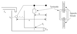
Figure 4. Integral action eliminates steady state offset, like adding a turnbuckle to the valve stem. If the buckle is turned in one direction, the stem is shortened and the valve opens; if turned in the other direction, the stem is lengthened and the valve closes, without a change in the tank level.
It is immaterial whether the disturbance is the inflow rate or some other aspect that affects either the inflow or outflow, or whether the level falls or rises as a response to the disturbance. If the disturbance persists, the process will not settle at the setpoint.
A method to eliminate steady state offset is to add integral action. But, that calculus terminology has little physical meaning, so to add understanding, consider the injection of a turnbuckle to the valve stem (Figure 4).
In a turnbuckle, the ends of the rods are threaded to fit into the threaded holes of the buckle. The threads go in opposite directions. So, if the buckle is turned in one direction, the two sections of the valve stem are pulled together, the stem is shortened, and the valve opens. If turned in the other direction, the stem is lengthened and the valve closes. This permits opening and closing of the valve without a change in tank level.
If you notice that the liquid level has risen, you know that some disturbance is acting, and the buckle needs to be turned to shorten the stem, to open the valve a bit more than the original, pre-disturbance position for the tank level. If the level rises a little bit, there is only a small upset, and the buckle only needs to be turned a little. In contrast, a large level deviation indicates a large upset has occurred, which justifies a large turnbuckle readjustment. And, of course, a level rise or drop would direct turns in the opposite direction.
So, let’s have an observer follow this rule: At each sampling, observe the level deviation from setpoint, and make an incremental change in the turnbuckle angle that's proportional to the level deviation. In Equation (3), ∝ represents the thread pitch (axial distance per angle), β is the proportionality rule to change angle due to level deviation from setpoint (angle per h deviation), and c=∝β is their product:
After the most recent sampling, the ith observation, control action changes the valve stem length from the previous length:
The sequence of the past two adjustments is:
Continuing to include past adjustments generates an equation that indicates how all of the adjustments have contributed to the current valve stem length change from the initial value, l0:
In Equation (6), the number of items in the sum is N = (t/∆t) ,where t is the total time that the controller has been in AUTO, and ∆t is the controller sampling interval. Multiplying and dividing the sum by ∆t reveals that the sum of rectangles (e-height times ∆t-base) is just the rectangle rule of integration, which can be represented by the calculus notation.
Note that, even though the integral symbol is used in Equation (7), no calculus procedure was used by the turnbuckle adjuster. If this were to be implemented by a computer, the Equation (4) adjustment in the valve stem length is not calculus, but a simple algebraic multiplication and addition. Further, in the computer, the subscripts are not needed. The assignment statement representing the Equation (4) action is U: = U + ce. Don’t let the integral symbol misdirect your understanding. There is no calculus to the doing of control.
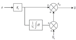
Figure 5. A block diagram of the standard form of the PI controller shows the integral value (the sum of incremental changes) is added to the initial bias to make the controller bias adjust at each sampling. The notation indicates the function (inside the box) and the function argument (the box input value).
A common form of the controller calculation is to incrementally sum (integrate) the scaled error, KC e, which means that the (c/∆t) coefficient needs to be divided by KC. Since the term (ΔtKc/c)only has dimensions of time, τi, one can represent the PI controller function as the block diagram of Figure 5. It shows the integral value (really, it's just the sum of incremental changes) is added to the initial bias to make the controller bias adjust at each sampling. The block diagram notation indicates the function (inside the box) and the function argument (the box input value). But again, don’t be thinking calculus, the integral operation is simply an arithmetic incremental accumulation.
In the standard form, KC is the controller gain that multiplies both the P and I terms, and the integral time, τi, divides the integral (which is actually calculated by incremental summation).
Recall, the purpose of the proportional action was to immediately counter the effect of a disturbance, but its problem is that it leaves a steady-state offset. The integral purpose was not to be the primary control action, but to remove the offset left by the P-action. Accordingly, tune the P first (KC) to set the aggressiveness of the controller, then adjust the I-action (τi) to remove the residual offset at a desirable rate.
Anticipated error and derivative mode
In the description of P-action, the controller acts on the initial impact of the disturbance on the CV. However, the initial reveal that a disturbance has happened might be a small CV deviation, but, if allowed to fully develop over time, it might evolve to a large value. The fully developed CV deviation, not the initial indication, represents the magnitude of the disturbance that's causing the CV to start deviating. With derivative action, the controller will take proportional action based on the anticipated error, not just on the initial reveal of the CV deviation. The question is how to forecast the anticipated error, the fully developed result of a disturbance?
If the process is linear and has a first-order response to a disturbance, then the model of how e would respond to a change in a disturbance, ∆d, is:
The value of eanticipated is the steady, fully developed, anticipated value.
Note that if the disturbance could be measured and the process gain to the disturbance were known, then eanticipated could be calculated from Kd (∆d) = eanticipated. However, those are often unmeasured and unknown. Fortunately, Equation (8) reveals that one can estimate the anticipated future error based on the current actuating error and its rate of change, the values of which are already known by the controller.
Equation (9) does not specify what the disturbance is. The deviation could indicate a confluence of several disturbances, including the MV. Equation (9) is called a “lead,” which should be familiar. It represents what a ball thrower must do to have a running target catch the ball. The ball must be thrown to where the receiver will be when the ball gets there. The PI controller with the P-action based on eanticipated is:
When Equation (9) is substituted into Equation (10) and rearranged, the PI controller with P-action on the anticipated error is the classical PID relation:
Although Equation (11) looks like calculus with its ∫ edt and (de/dt)representation, the integral is actually just the incrementally updated sum, and the derivative will be calculated from a numerical approach ((enew-eold)/∆t), which, again, is simple arithmetic subtraction and division.
PD-action is equivalent to P-action on the anticipated error. Whether D action is used or not, one still needs incremental adjustment to the bias, I-action, to remove steady-state offset.
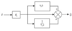
Figure 6. This block diagram of a PID controller uses the Laplace transformed notation, where s indicates the operation to take the derivative of the input to the function block, and 1/s indicates to integrate the input.
If the process measurement is noisy, the numerical derivative amplifies the noise impact. And, if the process is relatively quick to respond, there's no need to use the anticipated error concept. So, only use D-action on noiseless and slow-to-evolve processes.
In block diagram notation, the PID controller (a PI controller with P based on the anticipated error, and the incremental adjustment to remove steady state offset) is represented in Figure 6. The figure uses the Laplace transformed notation, where s indicates the operation to take the derivative of the input to the function block, and 1/s indicates to integrate the input. But, again, regardless of the symbols or calculus words to describe the functions all are simple arithmetic operations.
PID in summary
Proportional control is the simple concept of taking immediate proportional action on the actuating error, but P-only control, U = KCe + b0, with a fixed bias, leaves steady state offset. The user chooses the value for KC to set controller aggressiveness.
Integral action incrementally adjusts the bias to remove steady state offset. Note, although called “integral,” there's no calculus in the action in the incremental accumulation. The user chooses the value for τi to set the speed at which offset is removed.
Derivative action forecasts what the actuating error will be, as a result of past influences, if they're left uncontrolled. It's the lead commonly used in hitting a moving target. PD-action is equivalent to P-action on the anticipated error, and leaves steady state offset. Note, although called “derivative,” there is no calculus in the action of numerically estimating the CV rate of change. The user chooses the value for τd to lead the aim of the controller.
We communicate the PID procedure with calculus, or Laplace or Z-transforms, or other advanced mathematical symbols. With a bit of sarcasm, it seems the reason to use fancy mathematics is to make people think it's difficult, so they need to hire an expert. But, the reality is that the PID calculations are simple arithmetic procedures. By contrast, an expert’s focus on the mathematics distracts those intellects from the important aspects of control, such as structuring ratio, cascade and override, or choosing appropriate modifications, anti-windup and initialization procedures. The real experts are not necessarily the mathematicians of control theory. They are the ones who can implement control.
There are many modifications to the PID equation. Reset feedback, for example, is an alternate method to incrementally adjust the bias, which prevents integral windup, and is especially useful in override and constraint strategies. Another common modification is the rate-before-reset or interacting controller, which can be created if incremental changes to the bias are also based on the anticipated error. For a discussion of such modifications, see Rhinehart, R. R., H. L. Wade, and F. G. Shinskey in the Instrument Engineers' Handbook, Vol II, Process Control and Analysis, 4th Edition, B. Liptak, Editor, Section 2.3, "Control Modes – PID Variations," pp. 124-129, Taylor and Francis, CRC Press, Boca Raton, Fla., 2005.
For a procedure to tune the controller, see “Criteria and procedure for controller tuning” by R.R. Rhinehart (Control, Jan ’17, p. 54-55).
R. Russell Rhinehart, engineering coach, www.R3eda.com, has his PhD from North Carolina State University, and recently retired as a professor at Oklahoma State University to provide services to the practice community. He can be reached at [email protected].

