Making OT security engineering deserve its name

OT security engineering (development of security solutions for automation) is rarely done by OT engineers themselves. Here, we explain how to change that. First, we compare existing OT security engineering procedure models and identify their gaps, leveraging a method-agnostic thought model. Then, we’ll proceed to fill one of the identified gaps: the systematic analysis and modelling of the systems to be protected. Transferring this system model into a data model, potentially based on AutomationML, renders both the security engineering process and the implementation of security engineering solutions more efficient.
The necessity to include IT security in the development and operation of automated systems (Operational Technology, OT) has been identified by governmental agencies [1], [2], academia [3], and the industry [4]. But whose job is it to do this OT security engineering?
We believe that OT security can only be established if it is naturally and efficiently integrated into the engineering process of automation systems. Since profound knowledge of the relevant systems is the basis of systematic security engineering, OT security must be developed by those who know these OT systems best, the OT engineers. However, it will always stay an additional task and thus, needs to be as systematic and efficient as possible. But when looking for a coherent method leading from the first problem analysis to developing security solutions, OT engineers don’t often find anything close to what they’re used to from their own engineering disciplines.
OT security engineering: Where do we stand?
The objective of OT security engineering is the systematic development of security solutions. It includes the systematic identification of potential security risks as well as the development of organizational or technical security solutions. There are different approaches to define the operational field of security engineering; however, here we narrow it down to the following aspects:
- Problem definition, including goals and assumptions
- Reproducible deduction of solutions
- Systematic documentation of problems and solutions
Therefore, we focus on the design phase, not the maintenance or decommissioning phases.
We assume that security engineering is always embedded into a management system – based on standards like ISO/IEC 27001:2013 [5] or ISA/IEC 62443-2-1 [6] – that covers the entire life cycle, including audits and continuous improvement, while also considering interfaces to other organizations.
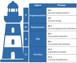
Figure 1: Security Engineering Thought Model: Layers and Process
Also, we consider security engineering with a focus on OT for comprehensive automation systems and networks. Procedure models that exclusively focus on software engineering (see [7]) will not be included; instead, we’ll look at those based on an interdisciplinary systems engineering approach. We will also include procedure models that were not explicitly developed for OT, but are still applicable.
There is one essential difference between security engineering and other engineering disciplines: Without unexpected incidents, there would be no need for security. Unlike other engineering disciplines, security engineering does not define functional requirements itself, but ensures the compliance to functional requirements defined by other engineering disciplines even during undesirable events.
Therefore, a risk analysis plays an essential role when defining requirements in security engineering. Consequently, many fragments for security engineering procedure models can be found in the context of risk management processes. The popularity of risk management also has a regulatory background: In Germany, for instance, OT security for critical infrastructures is mainly driven by the (German) IT security law [8], and the situation is comparable in other countries. In order to render OT security verifiable in audits, regulation commonly calls for an Information Security Management System (ISMS) that can be audited [9] – and risk management is a key aspect of every ISMS.
OT security engineering: A Thought Model
In order to compare and classify existing methods in OT security engineering without limiting ourselves to one particular procedure model, we developed a generic and method-agnostic thought model for security engineering.
Method-agnostic means that all existing procedure models and methods in the field of OT security engineering can be used within this thought model. This has been tried and tested in our own professional practice – mainly with operators of critical infrastructures and in the process industry, but also with manufacturers and integrators.
Figure 1 visualizes the basic structure of the OT security engineering thought model. It consists of four sequential layers into which existing methods can be categorized. The four layers can be seen as the levels of a lighthouse that each represent a crucial feature of our thought model: The individual layers systematically build on each other; no layer works without the one below it.
The purpose of the Function layer (FC) is to clearly describe the problem and establish preconditions, assumptions and groundwork to prepare and process all of the information that is needed for the subsequent layers.
In OT security engineering, a problem description always involves the identification of security objectives, or, more specifically, the identification of system functions that need to be protected (FC.1 Function Identification) as well as their dependency on people, hardware, software or organizational processes (FC.2 Dependency Analysis).
The Risk layer (RI) includes all methods that are used to identify (RI.1 Uncertainty Identification) or evaluate (RI.2 Uncertainty Evaluation) risks.
To guarantee method neutrality we use the word “uncertainties” as a general term to cover threats [10], hazards, vulnerabilities, attack trees [11–14], cyber fragilities [15], dependencies [16], petri nets [17] or similar concepts – depending on the chosen methods.
The term “uncertainties” matches the definition of “risk” that is used in the fundamental standards ISO 31000:2018-02 and ISO/IEC 27000:2018: “[risk is] the effect of uncertainty on objectives“ [18], [19].
The Requirements layer (RE) encompasses the definition of security requirements based on a risk analysis, or risk treatment (RE.1 Security Requirement Definition). Examples for frequently used requirement catalogues include the following:
- ISO/IEC 27002:2013 [20], parts of ISA/IEC 62443 series (e.g. [6], [21], and [22]),
- NIST Cybersecurity Framework [1],
- the German “IT-Grundschutz Compendium” [23],
- as well as several sector-specific security standards.
Security requirements within the third layer define what a certain security control is meant to accomplish – they do not define how that is implemented. This is what the uppermost Implementation layer “Implementation” (IP) aims at: the individual design (IP.1 Security Design) and implementation (IP.2 Security Implementation) of technical and organizational solutions that meet the security requirements previously defined.
If a procedure model covers all layers of the lighthouse model, "walking back downstairs" is possible at any time. In concrete terms this means:
- Each security solution can be traced back to the security requirements it is supposed to meet.
- Each security requirement, in turn, can be mapped to the uncertainties it is supposed to mitigate.
- And for each uncertainty it is possible to understand which function brings about this uncertainty and why.
When examining present procedure models and pre-existing methods (or method fragments), we consider two categories of procedure models: those within the context of a risk analysis and those within the context of (systems) security engineering.
Procedure models in the context of risk management
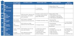
Figure 2: Comparison between procedure models in the context of risk management based on the security engineering thought model.
Different procedure models are available for risk management process, as described in ISO 31000:2018-02 [19], ISO/IEC 27005:2018 [24], ISA/IEC 62443-3-2 [25], the VDI/VDE 2182-1:2011 [26] and NIST SP 800-30r1:2012 [27] (based on NIST SP 800-39:2011 [28]). (Figure 2).
There aren’t many differences between procedure models regarding the Risk and Requirement layers, which is no surprise, because these layers represent the focus of risk management processes.
The same holds true when it comes to methods for those two layers: Plenty of methods are available and documented for these layers – even for OT environments [29].
However, the Function and Implementation layers deserve a closer look. As one would expect, there is little to no inclusion of the Implementation layer (IP) within procedure models focused purely on risk management, such as ISO 31000:2018, ISO/IEC 27005:2018 and NIST SP 800-30r1:2012. While designing and implementing security solutions is of crucial importance for security engineering, it is not part of the risk management process.
The design phase, which for complex solutions is absolutely essential to have in between requirement definition (RE.1 Security Requirement Definition) and implementation (IP.2 Security Implementation) phases, is missing in the popular risk management procedure models. These procedure models are often purely focused on mitigating certain risks with rather small-scale, less-complex measures. If the implementation of measures is regarded as part of the process in any manner, the design phase is usually skipped. This also applies to the VDI/VDE 2182:2011 standard, although not solely focused on risk management [26].
Altogether, these findings reveal the shortcomings of using procedure models based on risk management processes as security engineering procedure models.
The comparison at the Function layer yields a rather heterogeneous result.
As for the other layers, the ISO/IEC standards provide little detail for the FC layer. In the process step, they demand, among other things, the definition of a risk metric, risk tolerances, scope, and security objectives as well as an "understanding of the external and internal environment in which the organization operates" [25]. The same applies to NIST SP 800-39. NIST SP800-30r1 offers a little more detail: Under "Identify Scope,” it recommends the identification of organizational processes, systems (including surrounding architecture, if applicable) and a validity timeframe for the risk analysis results [27].
ISA/IEC 62443-3-2 contains the process step "Identify the System Under Consideration," which demands system identification including all of its points of access. The use of network maps and asset inventories is recommended, but no further specifications are made [25]. A distinctive feature of ISA/IEC 62443-3-2 is the explicitly defined process step ZCR3, which includes partitioning the system into zones and conduits, between the initial risk analysis (ZCR2) and the detailed risk analysis (ZCR5). In our thought model, definition of zones and conduits is also assigned to the FC layer because it involves understanding the systems’ criticality based on their functions and is used as an input variable for the detailed risk analysis.
VDI/VDE 2182-1 offers a "General Model" for OT security, which includes suggestions for input and output of the individual process steps [26]. For the FC layer of the thought model, however, it offers little in comparison to the further process steps: It requires a structure analysis as an introduction to its procedure model, which begins with a list of all assets. The standard roughly outlines what the result of this structure analysis is supposed to be, including "functions, interfaces and data flows" and "typical use-case scenarios including their related users,” but – unlike for its remaining process steps – ignores the question of how to proceed. The same holds true for roles and dependencies.
Protection goals are determined in the procedure model of the VDI/VDE standard, but, in contrast to all other considered procedure models, only after the threat analysis (equivalent to RI.1 Uncertainty Identification).
Procedure models in the context of (systems) security engineering
When looking for procedure models in the context of security engineering, it is noteworthy that there are a number of well-known publications that do not include a procedure model at all. Instead, they come with a pool of experience regarding security threats and best practices for security solutions, such as Ross Anderson in his book “Security Engineering” [30], though mainly focused on software engineering. The ICS-security-compendium of the German Federal Agency for Information Security (BSI) [2] and the works of Knapp/Langill [31], Macaulay/Singer [32] or Ralph Langer [15] further include helpful overviews on the characteristics of OT compared to IT – but also do not include a procedure model.
Similar to the above, mapping of the individual process steps to the thought model is captured in the following table (Figure 3). Again, this figure is read from bottom to top.
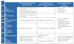
Figure 3: comparison of procedure models in the context of (system) security engineering based on the security engineering thought model.
NIST SP 800-160 is based on the international standard ISO/IEC/IEEE 15288:2015 regarding “Systems and Software Engineering” [7], complementing it with systems security engineering. For that purpose, it describes a systems security engineering framework, but lacks a flow sequence.
“Consequence-driven Cyber-informed Engineering” (CCE) is an engineering approach of the U.S. Idaho National Laboratory (INL) designed to systematically meet risks with particularly severe consequences within the OT environment [33], [34].
Stuart Jacob’s book on “Security Systems Engineering” might not be OT-specific, but it provides a security life cycle (albeit not very detailed) that is suitable for implementation within a management system [35].
Again, all procedure models completely cover the RI and RE layer, mostly referring to the risk management procedure models previously examined. Yet they can provide additions that are missing in the risk management procedure models.
As one would expect, the security engineering procedure models provide more guidance on the IP layer than the risk management models. Both NIST SP 800-160 and Jacobs call for a design phase, creating concepts of security solutions based on the predefined requirements before starting the implementation. They also demand a clear reference to which security requirements are covered by which security solution.
Furthermore, NIST SP 800-160 requires, as it is common for security engineering, the guaranteed traceability of whether the solution actually meets its security requirements.
The FC layer is filled with similar content in systems security engineering procedure models as in the aforementioned risk management procedure models. NIST SP 800-160 additionally demands that the effect of the security solution must be measurable, noted in the implementation process step analyzed earlier [35].
However, the INL CCE procedure model is much more concrete. It suggests to first identify the most critical functions and services, defined as those for which security incidents would have the most severe consequences. Therefore, the process step is labelled as “Consequence Prioritization.” In the next step, “System of Systems Breakdown,” the most critical functions and services are divided into their sub-systems and relevant communication channels [33].
Gaps in procedure models and methods
The FC layer methods leave the most room for improvement. This was already revealed when comparing the different procedure models: Most of them defined what the result of the FC process step should be, even though they already differ considerably in this aspect. However, regarding the question how the operator should get to this result, all of the aforementioned procedure models remain vague or even explicitly exclude this question from their scope – even when they do outline the “how” for their other process steps.
Of course, process models do not necessarily have the purpose of providing concrete methods. Cherdantseva et al. [29] have conducted an extensive comparison of risk methods for OT considering all process steps included in ISO 31000:2018-02 or ISO/IEC 27005:2018; thus, taking into account the lower three layers of our OT security engineering thought model (Figure 2).
Their comparison of concrete methods yields similar results as those indicated by our comparison of procedure models. While there is a wide range of methods for the identification, analysis and evaluation of risks (the RI layer of the thought model), there is little to nothing available regarding the FC layer: “Little attention is received by the context establishment stage. It is typically assumed that a user of a risk assessment system knows the system and its interdependencies well” [29].
This deficiency has various consequences.
Because there is no FC layer method taking an OT point of view and resulting in defined functions to be protected, the security objectives often are defined as confidentiality, integrity and availability of data and information [2], [31], [32] as known from the IT security domain.
Even in a different rank order (availability first), these security objectives do not cover protection needs for operational technology from an OT engineers’ point of view. In OT, focus is on smooth execution of physical processes according to requirements, rather than protection of data integrity and availability. In this context, "according to requirements" refers to the economic and "safe" (in the sense of functional safety) fulfilment of functional requirements.
The lack of FC methods also has consequences at the RI layer. Risk analysis methods often begin without any basic analysis of the system to be protected. Instead, elaborated hazard checklists are being used as a starting point in an attempt to map them to the systems that are retroactively under consideration.
Where do these extensive hazard checklists come from? A lot of time and money is spent on gathering general information on threats; for example, with the help of threat intelligence [36]. This tendency, together with the so-called “all-hazards approach” [9] recommended for instance by the German Federal Agency for Information Security (BSI), results in constantly expanding threat catalogues (e.g. ISO/IEC 27005:2018 [24], NIST SP800-30r1 [27], IT-Grundschutz [23]). While these hazard lists are a valuable source of inspiration to derive threats based on sound system knowledge, they are not a good starting point before having done ones’ homework on the FC layer of the layered blueprints thought model.
The lack of an FC methodology also means that security engineering misses the chance to build upon OT engineers’ valuable system knowledge. However, this makes the development of reasonable, pragmatic security solutions for the system at hand extremely unlikely.
Vice versa, OT engineers are missing the opportunity to carry out a structured dependency analysis of their own systems that would not only add to their system knowledge, but enable them to take responsibility for their own systems’ security. Often, OT engineers do not identify with the security engineering process and arrive at the conclusion that they can or must leave that responsibility to others.
As a result, it is mainly security experts who are in charge of OT security engineering. Due to a lack of knowledge of OT characteristics, they find it difficult to develop security solutions that fit into the operating regime of the OT environment. This leads to a lack of acceptance of the rather new discipline of OT security engineering within its most important target group – the OT engineers themselves.
There is yet another widespread problem which a systematic FC layer methodology can help to solve: In their conclusion, Cherdantseva et al. criticize the lack of a comprehensive method that guides seamlessly through all process steps considered in their comparison: “There is clearly a need for a comprehensive method which would cover all stages of the risk management process and deal with all key risk management concepts“ [29]. As described earlier, an FC methodology must result in an information basis related to the systems that need to be protected and tailored to security engineering needs. This result can represent the linkage between the individual process steps that is systematically extended in all further steps.
A use-case based method for the Function layer
To close the previously identified gaps in existing procedure models and methods, the authors developed a method for the FC layer.
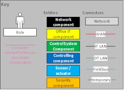
Figure 4: Key for the network model and communication analysis
For this method, the following objectives were pursued:
- The method shall be realizable by OT engineers themselves and meet their way of thinking.
- The method shall include a comprehensive state analysis that thoroughly covers technical aspects, but also processes and human interactions.
- The method shall be realizable with adequate time and effort.
- The results of this method shall be usable for the further layers, so they can represent a linkage between all layers of the thought model.
Its most important feature is focusing on use-cases rather than single systems as its main reference unit. These use-cases depend on people, systems and communication, and these dependencies are modelled in a standardized way.
FC.1 Function Identification
Defining OT security objectives merely as data confidentiality, availability and integrity is not precise enough because unobstructed operation of physical processes is paramount.
Of course, “unobstructed operation of physical processes” has to be further defined in order to provide a useful working base for security engineering. Process step FC.1 aims in this direction by identifying all critical functions of an organization that are to be protected by security engineering. This step is essential, but does not represent a major addition to the procedure models that have been previously referenced and compared.
At this point, functions are considered from a purely organizational point of view. The focus lies on human interactions and organizational (business) processes rather than on the technical implementation.
It is reasonable to separate this step from the following dependency analysis, because other roles in the organization usually can contribute to that. While the technical dependency analysis requires technical knowledge about the implementation of a function, the knowledge about (business) processes usually lies in management roles.
FC.2 Dependency Analysis
The next step contains a detailed analysis of the dependencies of the functions to be protected. A dependency can be defined as “everything that needs to work to ensure the function can run according to its requirements.”
Of the identified functions, those depending on the use of IT or OT systems (hence “use cases”) are picked and analyzed further in a dependency analysis (FC.2).
The basis for a dependency analysis is a documentation of the network at hand. If this documentation does not exist already, it must either be compiled beforehand or during the dependency analysis process. However, in order to keep the dependency analysis efficient, it should not be not based on the full level of detail of asset inventories or network maps. Rather, the level of detail should be reduced to the level of a so-called network model.
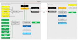
Figure 5: Exemplary network model of a drinking water supplier.
Network model
Purpose of the network model is the explicit and technically sound documentation of the scope, the assumptions and the preconditions for the development of a security solution.
In contrast to a network map, the network model is not supposed to be a complete network documentation. Therefore, it represents all IT and OT systems and human roles (hereafter collectively referred to as entities) as well as all communication links (hereafter referred to as relations) reduced to the aspects relevant from a security point of view.
The challenge in creating a network model lies in identifying how entities and relations must be distinguished from a security point of view. There are no general rules for that, but the following approach is recommended.
As a first step, it helps to realize what makes the network complex. In this complexity, recurring patterns must be identified and defined in classes. Classes can reduce the complexity of various entities, relations and locations.
In order to differentiate between classes, it can be helpful to consider whether they differ from a security point of view. Taking security into account, even seemingly “identical” entities can differ, for instance, their operating systems, applications, usage scenarios or roles with regard to identified functions can vary. For all of the identified classes, only one instance needs to be modelled in the network model.
As a slightly simplified example, a network model of a drinking water utility is presented in Figure 5 (Figure 4 contains the key to this network model and the following communication analysis).
The network model was created by the OT engineers of the drinking water utility themselves, with support from the authors.
In this example, the complexity of the initial network map was mainly caused by the variety of different locations and their heterogenic wide area network (WAN) connections. In the network model, locations could be classified as control room locations or field locations. For both location classes, one instance for all existing components and one instance for all existing WAN-connections was modelled.
It is noteworthy that in case of the presented example, not a single real location looked exactly like the modelled locations; the model rather represents an aggregation of all possible components that were present in any location of the respective location class.
Since the network model serves as the foundational documentation of the scope and the technical assumptions for all further sub steps in the security engineering process outlined in the thought model, simplifications should be done with great care. An entity or a relation that is not modelled within the network model will not be included in the following analysis. Thus, the network model represents a crucial step to break down the complexity of the security engineering process. At the same time, the system under consideration and its security objectives are rendered more tangible because they are explicitly documented in a technically sound manner that is intuitive to understand for all people involved in security engineering. From the authors’ combined experience, agreeing on the network model takes some time but afterwards, everyone in the security project is on the same page (and more often than not, OT engineers are keen to get their hands on that network model because it’s the closest to maintaining a network overview they ever were).
Communication analysis of the use cases
Based on use cases, the security objectives are defined explicitly in the communication analysis.
Use cases describe communication sequences between entities that ensure critical functions, namely IT / OT systems and human roles, where applicable. This is a wider definition of the term use cases than in software engineering [38]. Because security engineering use cases display interactions between complex automation networks, the level of detail is lower than in software engineering. It is not software components that interact, but complex systems composed of hard- and software and in some cases human beings.
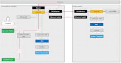
Figure 6: Partial network model for the use case "Controlling a field location."
However, indications for potential use cases can also be provided by the network from a bottom-up perspective: Each and every entity and relation within the network model must be included in at least one use case. This rule of thumb can also be used as a completeness check for the use case identification.
There may well be more than just one use case for one function. For identifying potential use cases, both the users’ “black box” perspective and the administrators’ “white box” perspective are relevant.
In our experience, a graphical documentation is not only most efficient and most intuitive, but also sparks most fruitful discussions among OT engineers doing security engineering. Hence, the result of the dependency analysis is fully graphical, building upon the network model.
For each use case, all dependencies – that is, all communication sequences between entities that ensure critical functions – are modelled in two different presentation formats: the partial network model and the sequence diagram. These are demonstrated in Figures 6 and 7 for the exemplary use case “Controlling a field location.”
Both formats show all roles that are able to control as well as all classes and components that can be used for controlling. Furthermore, they contain the complete communication including all involved protocols that are needed for controlling. The partial network model additionally demonstrates how the use case’s entities are placed within the complete network. The sequence diagram, in turn, contains the chronological order of the communication sequences as well as all transmitted information. Therefore, both formats combined provide a complete graphic representation of the use case.
The completed communication analysis sums up what needs to work in order to sustain the critical functions identified in step FC.1.
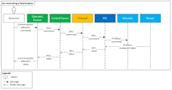
Figure 7: Sequence diagram for the use case "Controlling a field location."
Also, it facilitates a more pragmatic description of security objectives. Instead of protecting data availability, confidentiality and integrity, the aim is to protect the outlined use cases from failure or manipulation.
Compared to thinking in single assets, thinking in use cases has some major advantages:
- First, while an asset is mostly technology, a use case is the glue that connects the three aspects of people, processes, and technology.
- Use cases connect assets with their purpose, which you need to understand to evaluate asset criticality, but also possible consequences of threat scenarios.
- Also, use cases reduce complexity and help you reduce your system understanding to the essential. While you have a number of assets in the order of magnitude of maybe tenth of thousands, use cases typically come in the order of magnitude of tenth to hundreds, depending on company size.
- Use cases are also easier to maintain because even when their realization changes, a company’s use cases mostly remain static.
Maybe most important: Thinking in use cases is more intuitive for automation engineers than listing single assets, and thus they are a really good guidance if you want to quickly understand – and systematically model – what a system’s most important functions are and how they work. Not only do use case-based security objectives require deeper system knowledge and a more careful identification of its most critical functions, they can also completely be defined by OT engineers themselves, meeting their mind-set and their understanding of what exactly needs to be protected.
A data model for the Function layer
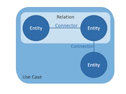
Figure 8: Schematic sketch of the data model
The implementation of security measures is never first priority for OT engineers. Security requirements are always second in line behind functional requirements for an OT system. Also, they need to fit into everyday operations. Thus, it is crucially important that engineering and implementation of security solutions work as efficiently as possible.
The results of the FC layer methodology proposed earlier can most efficiently serve as a common information base for the subsequent layers if they are machine readable. Thus, what is needed is a data model for the thought model.
This data model already helps at the FC layer itself for an automated visualization of network model, partial network model and sequence diagrams. However, its true potential lies at the Implementation layer (IP). Here, a data model could provide the basis for exporting security engineering results as configurations, for example to a configuration management database.
A slightly modified entity-connector-relationship-model is used as the basis for the object-oriented data model. Figure 8 shows its schematic sketch. A UML class diagram of the data model is provided in Figure 9. The following definitions apply:
- Entities are either components (assets) or human roles / operators.
- Connectors are, for example, software (between operators and system) or protocols (between two systems).
- A relation consists of two entities and one connector.
- A use case includes a number of relations.
Usage for the subsequent layers
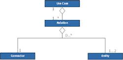
Figure 9: UML class diagram of the data model.
Using the FC layer methodology as described above pays off for the network model and use case model layers, because its results build the foundation for all subsequent process steps.
This section explains how to use the described FC layer methodology for the following layers of the method-agnostic thought model, regardless of the method that is used in these layers.
Risk layer (RI)
Once the security objectives are defined as use cases in process step FC.1, security objectives can be more pragmatically defined as availability, integrity and confidentiality of a certain function or use case, but not of data or information. When at the RI layer of the thought model, this makes identifying uncertainty scenarios corresponding to these security objectives more straightforward: For each use case, it is explicitly asked: “What could go wrong?”
There are basically two possible types of uncertainty scenarios for each use case. First, those that lead to the failure of the use case in a way that the function it is supposed to guarantee is no longer given, corresponding to the availability security objective. Second, those scenarios involving the manipulation or misuse of the use case for unwanted purposes, corresponding to the integrity/confidentiality of this function.
Also, uncertainty scenarios can be identified as “misuse cases” or “abuse cases” in process step RI.1. Like use cases, the concept of abuse cases is known in software engineering. Abuse cases may be displayed in the same way as the “intended” use cases, but represent unintended and unwanted scenarios. Same holds true for the data model, where abuse cases can be modelled object-oriented, just like the use cases developed at FC layer.
When deducing uncertainties, the threat catalogues can serve as a source of inspiration to ensure that all potential threat sources are considered. Still, every risk should result from the use cases individually identified for the system at hand.
Table 1 contains examples for the use case “Controlling a field location” presented in Figure 6.
There are several advantages to this approach.
| Uncertainty | Use case failure or manipulation? |
| Failure of a PLC due to noncompliance with the maintenance process | Failure (controlling impossible) |
| Software error at gateway | Failure (controlling impossible) |
| Man-in-the-middle attack against the fieldbus protocol | Manipulation (unauthorized control commands) |
| Social engineering attack against the operator | Manipulation (operator is persuaded to give defective control command) |
| ... | ... |
First, risks based on uncertainties that include a concrete scenario for the individual system can be more soundly evaluated during the uncertainty evaluation (process step RI.2) than generalized risks from a threat catalogue where the relation to the considered system has to be retrospectively established. It is precisely this retrospective reference to the real systems that often seems artificial and leads to the concept of risk analysis being frowned upon by practitioners.
Second, the holistic consideration of use cases as interactions between humans and IT/OT systems makes sure uncertainties due to faulty processes or human errors are not overlooked.
Third, because the OT engineers are able to define and analyze their use cases themselves, they can also conduct the uncertainty identification. Same holds true for security requirements: If the abuse case is well understood, the deduction of its prevention or mitigation by security requirements (RE layer) is not much more than a logical conclusion.
Requirement layer (RE)
Using results created on the FC layer and enhanced on the RI layer is also beneficial when defining the security requirements on the RE layer.
If the lower thought model layers were thoroughly carried out, it should be well documented which aspect of a threatened use case can lead to a risk and how. The deduction of security requirements can therefore be seen as a logical conclusion to the uncertainty and risk analysis, as Table 2 demonstrates for the uncertainties identified in Table 1 for the use case “Controlling a field location.” Just as the previous ones, this step can easily be conducted with an OT engineer’s knowledge.
Similar to the threat catalogues at RI layer, established requirement catalogues can offer orientation for requirement definition. Also, compliance demands can be met during the security requirement definition. Thus, security requirements can entirely be based on the analysis conducted on the function and risk layers, or they can be complemented by additional requirements, for example regulatory requirements.
Implementation layer (IP)
The information base (and the data model) that was begun on the FC layer and systematically enhanced on the subsequent layers is already quite extensive when the Implementation layer (IP) is reached.
| Uncertainty | Security Requirement |
| Failure of a PLC due to noncompliance with the maintenance process | Improvement of maintenance process documentation, introduce four-eye principle |
| Software error at gateway | Regular maintenance for critical software, redundancy |
| Man-in-the-middle attack against the fieldbus protocol | Encryption, authentication, restricted access, network segmentation |
| Social engineering attack against the operator | Role-specific awareness training, four-eye principle |
When a security concept is created based on this groundwork, all of this information should be included. This guarantees the maintainability of the implemented solution based on the security concept. If a solution needs to be altered after installation, the underlying security requirements are only one “staircase” in our thought model’s lighthouse away. In the same manner, it is always transparent which uncertainty these requirements result from and, in turn, due to which use case the uncertainty was introduced.
Because these thought-model “staircases” are designed and climbed by the OT engineers themselves, they can react flexibly when further changes become necessary. In other words, the OT engineers themselves can take responsibility for the security of their own OT systems. At the same time, as risk owners, they can choose adequate solutions that fit into their individual operations.
Another benefit is the usage of the FC layer analysis for designing solutions. After completion of the communication analysis, a complete communication matrix of the network model, including all communication partners and protocols for each component, has been developed. This communication matrix is an excellent basis for network segmentation, firewall rules and hardening guidelines. When the communication analysis is carefully created, all communication that isn’t modelled in any use cases is not required for sustaining the functions under consideration and, thus, can be blocked.
Also, the categorization of entities (including human roles) based on their security characteristics that was done when creating the network model can be used as a basis for standard configurations, group policies and roles for authorization concepts.
To round things up, if the information at FC layer is also complemented by a machine-readable version in the form of the data model described earlier, the aforementioned configurations can also be created (semi) automatically and transmitted into operational systems.
Conclusion and outlook
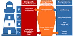
Figure 10: AutomationML as a common interface for security engineering (Source: AutomationML e.V.)
The thought model and the comparison of existing security engineering procedure models and methods in the first part of this article should help systematize OT security engineering. It is also meant to simplify the discourse about OT security engineering and inspire collaboration of OT engineers and IT security experts by providing a common “language.”
The methodology for the lowest thought model layer shall not only close one of the existing gaps within the compared procedure models, but close it in a way that empowers OT engineers to do OT security engineering themselves.
However, security never has highest priority for OT engineers, but is always second in line behind functional requirements. Thus, security engineering needs to be efficient.
The proposed thought model, the use case-based methodology including network model and communication analysis, as well as the corresponding data model are just the first steps toward a goal that is illustrated in Figure 10.
In order to gain efficiency, it is promising to have tools that support the security engineering process, as opposed to tools that substitute the security engineering process. Existing tools can be helpful by:
- integrating information derived from these tools into the security engineering process, and
- extracting information from it.
In the resulting process visualized in Figure 10, the security engineering process is marked in blue, and existing tools are marked in red.
For example, there is great potential in using existing tools for network administration, such as inventory software, as an input for the security engineering process or in generating configurations for Configuration Management Databases (CMDB) as an output of the security engineering process.
These tool types can rarely be found in one product, though. Also, it would not match the method-neutral approach of the OT security thought model to be dependent on one single tool vendor. Additionally, taking into account the high interdisciplinarity of engineering processes for automated plants, security engineering information should be accessible for neighboring engineering disciplines by using their established formats.
Consequently, a standardized, open interface between existing tools and the security engineering process is needed (marked orange in Figure 10). A promising candidate is AutomationML (AML), a standardized data format for integrating various engineering disciplines [37], [38].
If “Security by Design” is to be taken seriously, OT security engineering must blend into the existing engineering processes of an automated plant. Therefore, security engineering needs to be conducted by OT engineers, using methods that match their mind set and efficient tools that match their engineering process.
Let's make OT security engineering a true engineering discipline.
Resources
[1]NATIONAL INSTITUTE OF STANDARDS AND TECHNOLOGY: Framework for Improving Critical Infrastructure Cybersecurity (2014)
[2]FEDERAL OFFICE FOR INFORMATION SECUIRTY (GERMANY):ICS Security- Compendium (2013)
[3]FRANCIA, GUILLERMO A.; THORNTON, DAVID; DAWSON, JOSHUA: Security Best Practices and Risk Assessment of SCADA and Industrial Control Systems, S. 7
[4]NAMUR E. V.: NE 153 “Automation Security 2020 – Design, Implementation and Operation of Industrial Automation Systems” (2015)
[5]ISO/IEC 27001:2013: Information technology - Security techniques - Information security management systems – Requirements (2017)
[6]IEC 62443-2-1:2010: Industrial communication networks. Network and system security - Part 2-1: Establishing an industrial automation and control system security program (2010)
[7]ISO/IEC/IEEE 15288:2015: Systems and software engineering — System life cycle processes (2015)
[8]Gesetz über das Bundesamt für Sicherheit in der Inofrmationstechnik (BSI-Gesetz - BSIG) (2015)
[9]FEDERAL OFFICE FOR INFORMATION SECUIRTY (GERMANY):Orientierungshilfe zu Inhalten und Anforderungen an branchenspezifische Sicherheitsstandards (B3S) gemäß § 8a (2) BSIG (2017)
[10]SHOSTACK, ADAM: Threat modeling: designing for security. Indianapolis, IN: Wiley, 2014 — ISBN 978-1-118-81005-7
[11]BYRES, ERIC J; FRANZ, MATTHEW; MILLER, DARRIN: The Use of Attack Trees in Assessing Vulnerabilities in SCADA Systems, S. 9
[12]BAIARDI, F.; TELMON, C.; SGANDURRA, D.: Hierarchical, model-based risk management of critical infrastructures. In: Reliability Engineering & System Safety Bd. 94 (2009), Nr. 9, S. 1403 –1415
[13]CHITTESTER, CLYDE G.; HAIMES, YACOV Y.: Risks of Terrorism to Information Technology and to Critical Interdependent Infrastructures. In: Journal of Homeland Security and Emergency Management Bd. 1 (2004), Nr. 4
[14]GUAN, JIAN; GRAHAM, JAMES H.; HIEB, JEFFREY L.: A digraph model for risk identification and management in SCADA systems. In: Proceedings of 2011 IEEE International Conference on Intelligence and Security Informatics. Beijing, China: IEEE, 2011 — ISBN 978-1-4577-0082-8, S. 150 –155
[15]LANGNER, RALPH: Robust control system networks: how to achieve reliable control after Stuxnet. New York: Momentum Press, 2012 — ISBN 978-1-60650-300-3
[16]THE OPEN GROUP: Dependency Modeling (O-DM) - Constructing a Data Model to Manage Risk and Build Trust between Inter-Dependent Enterprises (2012)
[17]HENRY, MATTHEW H.; LAYER, RYAN M.; SNOW, KEVIN Z.; ZARET, DAVID R.: Evaluating the risk of cyber attacks on SCADA systems via Petri net analysis with application to hazardous liquid loading operations. In: 2009 IEEE Conference on Technologies for Homeland Security. Waltham, MA, USA: IEEE, 2009 — ISBN 978-1-4244-4178-5, S. 607 – 614
[18]ISO/IEC 27000:2018 - Information technology — Security techniques — Information security management systems — Overview and vocabulary (2018)
[19]ISO 31000:2018-02 Risk management – Guidelines (2018), S.24
[20]ISO/IEC 27002:2013 Information technology -- Security techniques -- Code of practice for information security controls (2013)
[21]IEC 62443-3-3:2013: Industrial communication networks - Network and system security - Part 3-3: System security requirements and security levels (2013)
[22]IEC62443-4-2:2018: Security for industrial automation and control systems - Part 4-2: Technical security requirements for IACS components (2018)
[23]FEDERAL OFFICE FOR INFORMATION SECURITY (GERMANY): IT-Grundschutz-Compendium. Edition 2019. Cologne: Bundesanzeiger Verlag, 2019 — ISBN 978-3-8462-0906-6
[24]ISO/IEC 27005:2018 Information technology -- Security techniques -- Information security risk management (2018)
[25]IEC 62443-3-2, FDIS 2019: Security for industrial automation and control systems –Part 3‑2: Security risk assessment for system design (2019)
[26]VDI/VDE 2182 Blatt 1:2011-01: IT-security for industrial automation - General model.
[27]NIST SP 800-30r1: Guide for conducting risk assessments. Gaithersburg, MD: National Institute of Standards and Technology (2012)
[28]NIST SP 800-39: Managing information security risk: organization, mission, and information system view. Gaithersburg, MD: National Institute of Standards and Technology (2011)
[29]CHERDANTSEVA, YULIA; BURNAP, PETE; BLYTH, ANDREW; EDEN, PETER; KEVIN, JONES; STODDART, KRISTAN: A review of cyber security risk assessment methods. In: Computers & Security, Vol. 56, pp. 1-27 (2016)
[30]ANDERSON, ROSS: Security engineering: a guide to building dependable distributed systems. 2. ed. Indianapolis, Ind: Wiley, 2008 — ISBN 978- 0-470-06852-6
[31]KNAPP, ERIC D; LANGILL, JOEL THOMAS: Industrial network security securing critical infrastructure networks for smart grid, SCADA, and other industrial control systems. Waltham, MA: Syngress, 2015 — ISBN 978-0-12-420184-2
[32]MACAULAY, TYSON; SINGER, BRYAN: Cybersecurity for industrial control systems: SCADA, DCS, PLC, HMI, and SIS. Boca Raton, FL:CRC Press, 2012 — ISBN 978-1-4398-0196-3
[33]FREEMAN, SARAH G.; ST MICHEL, CURTIS; SMITH, ROBERT; ASSANTE,MICHAEL: Consequence-driven cyber-informed engineering (CCE) (Nr. INL/EXT 16-39212, 1341416), 2016
[34]BOCHMAN, ANDY: The End of Cybersecurity. In: Harvard Business Review (2018)
[35]JACOBS, STUART: Engineering information security: the application of systems engineering concepts to achieve information assurance. 2. Ed.: Wiley-IEEE Press, 2015 — ISBN 978-1-119- 10472-8
[36]STEFFENS, TIMO: Threat Intelligence - IT- Sicherheit zum Selbermachen? In: heise.de (2016)
[37]SCHMIDT, NICOLE; LÜDER, ARNDT: AutomationML in a Nutshell (2015)
[38]DRATH, RAINER; JOHN, MICHAEL; LÜDER, ARNDT; PAULY, JOHANNA; PRINZ, JOSEF;
[39]RENTSCHLER, MARKUS; RIEDL, MATTHIAS; SCHLEIPEN, MIRIAM; U. A.: AutomationML Brochure, AutomationML e.V. ()
