A straightforward explanation of feedforward control

Greg: The use of feedforward control is often a missed opportunity because of the misinformation in the literature and the lack of guidance on implementation. Here we get a straightforward understanding and approach to feedforward control from Peter Morgan, who as leader of the ISA 5.9 Standards and Practices (S&P) working group for PID algorithms is responsible for generating a technical report to help industry more effectively use this and other PID capabilities. Assuming we have resolved the issues of properly using the PID Form discussed last month, what is the what, when and where of feedforward?
Peter: Where the control system or process allows for the measurement or inference of loading on the process, feedforward can provide a simple and effective improvement in control, providing anticipatory action at the controller in advance of a change in the controlled process variable.
There are two recognized forms of feedforward, namely “feedforward sum” and “feedforward multiply” (Figure 1). While vendors usually provide both forms of feedforward, “feedforward sum” typically sees more use.
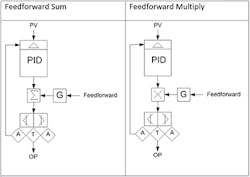
Figure 1: “Feedforward sum” (left) adds the feedforward signal to the result of the PID algorithm, whereas “feedforward multiply” (right) outputs the product of the feedforward signal and the result of the PID algorithm.
“Feedforward sum” adds the feedforward signal to the result of the PID algorithm, whereas “feedforward multiply” outputs the product of the feedforward signal and the result of the PID algorithm. Generally speaking, when the feedforward signal is an index of the loading on the process, the feedforward gain (if provided as a configurable parameter) should be set to unity, so that the feedforward action required is fully specified by any external characterization required.
One caution regarding the implementation of feedforward is that it should done in the PID block and not externally, because doing so would require additional logic to provide bumpless transfer of the loop from manual to auto, and prevent integral wind-up when the downstream control element is in limit.
Feedforward sum may be incrementally implemented so that the change in the feedforward signal adds to the result of the PID algorithm. This has the advantage of allowing feedforward to be enabled or disabled at the control block without disturbing the output. This feature should not be dismissed, because I've known a unit to trip when the feedforward was inadvertently disabled externally, the feedforward signal suddenly going to zero!
Greg: How about a feedforward application example?
Peter: In a common power industry application shown Figure 2, the output of the combustion air controller is forwarded to the furnace pressure controller to anticipate the required adjustment of the induced draft fan inlet guide vanes in order to improve furnace pressure control during boiler load adjustment. Interestingly, the application of feedforward for furnace pressure control is so well recognized as improving response and furnace safety that it is mandated by NFPA. Another example of the application of Feedforward (although not normally recognized as such since it has a long history of use) is “three element” boiler drum level control. In this application, the steam flow signal is forwarded to the drum level controller as a feedforward signal to establish the demand for feedwater flow and maintain the inventory of water in the boiler with only trimming action by the level controller PI (mostly P) action.
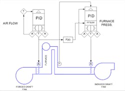
Figure 2. The application of feedforward for furnace pressure control is so well recognized as improving response and furnace safety that it is mandated by NFPA.
Greg: How do you adjust feedforward parameters?
Peter: The feedforward signal can be characterized online. With the feedforward disabled at the controller, but the controller operating in auto, process loading can be gradually increased and the relationship between the load index signal and controller output established by noting the controller output in the steady state at various process loads. The non-linear function in the feedforward path can then be programmed to give the required advanced positioning of the manipulated variable (in the example given, the ID Fan inlet guide vane position).
Feedforward magnitude and timing problems are indicated when the controlled process variable changes in the opposite direction to that resulting from the load disturbance when the loop is operating in the feedback mode only. If opposite direction response occurs before feedback action correction takes place creating inverse response, the feedforward is arriving too soon indicating a feedforward delay or lag must be increased or lead decreased. If the opposite direction response occurs after the feedback correction, then the feedforward delay or lag must be decreased or lead increased. If the opposite direction response is the only response seen, the timing is right but the feedforward gain is too large. If there is no response in either direction, feedforward is perfect. In reality, it is better to be a little conservative with the feedforward gain so that changes in the valve and process dynamics do not cause disturbances from the changes in feedforward timing or gain needed.
The historical data typically available on large industrial plants should not be overlooked as a means of correcting or fine tuning feedforward action. The sampled data from process information systems can be used to confirm or establish the relationship between the load index and the feedforward signal value.
Greg: A feedforward with the wrong timing or gain creates confusion and can do more harm than good. In some cases a smarter feedforward is needed to account for an unmeasured disturbance that might be in the same direction as the feedforward correction making the control worse than if there was no feedforward. For example, in distillation control, a feed composition disturbance may be driving the tray temperature up. If a feedforward from a feed flow increase is used that increases steam or reduces reflux, the feedforward would be further increasing the temperature making the control worse. In these cases, a process variable (PV) rate of change with a good signal-to-noise ratio described in the Control Talk “Simulation Breeds Innovation” can be used to make feedforward smarter, so that it doesn’t amplify unmeasured disturbances. How is the user to identify which form of feedforward to use?
Peter: Feedforward type is sometimes wrongly selected. Typically, I have seen “feedforward multiply” selected when “feedforward sum” is the obvious choice. A “feedforward multiply” is rarely used but is sometimes seen for flow control of streams for inline blending or plug flow reactions and speed control of extruders, sheet lines and conveyors. The distinguishing application conditions here that may justify “feedforward multiply” are deadtime dominance and accurate flow or speed measurements. If ratio control is used here, the PID corrects the ratio, which is effectively a “feedforward multiply.” Most ratio control systems for unit operations with a lag dominant response (e.g., agitated biological and chemical reactors, evaporators, crystallizers, distillation columns, heat exchangers, and neutralizers), have a ratio set by the operator and a bias corrected by the primary PID, which is effectively a “feedforward sum.”
Greg: Often, textbooks show a plot of a manipulated variable versus the feedforward variable and cite that if the intercept changes, a feedforward sum should be used, and if the slope changes, a feedforward multiplier should be used. Most people who are not on the frontlines think that the intercept is usually near zero and it is the slope that changes, consequently recommending a feedforward multiplier. Some may even cite the advantage of the multiplier compensating for a process gain that is inversely proportional to feed flow. This is the wrong conclusion for many reasons. Most volumes have enough mixing where the process time constant increases as the flow decreases compensating for the increase in process gain. Even more significantly is the fact that most primary process variables, such as temperature and pH, have a measurement error that is more an offset than a span error (e.g., thermocouple drift and liquid junction potential shift). Furthermore, span errors do not show up except for very large changes in the process variable and can be readily compensated by an offset adjustment. Multivariable predictive control (MPC) has a 40-year history of great success controlling and optimizing complex processes by a simple bias correction of trajectories that is a fraction of the error between the predicted and actual controlled variable. Finally, feedforward multipliers introduce great challenges due to multiplicative effect of errors in feedforward gain and may not even be an option in modern control systems.
Greg: Does the addition of feedforward to a loop reduce reliability, and what steps can be taken to avoid the impact of feedforward signal faults?
Peter: Feedforward does add a dependence on an additional signal in a control loop. However, if the feedforward is based on a load index signal that is already used for closed loop control, there may be little change in system reliability. Of course, measurements of established reliability for control should be used, but with simple additional provisions, the effects of signal failure can be minimized. For instance, with a modern DCS, PV Status can be used to trip the controller to manual, or (when the feedforward is incrementally implemented) the feedforward can be disabled. For critical systems, transmitter redundancy should be considered for reliability improvement.
Greg: Feedforward control is used for decoupling. Here, the output of the less important controller is added to the output of the more important controller. This half decoupling is sufficient to break the interaction. Feedforward gain, deadtime and lag time should be adjusted for best results. For steam header pressure control, the output of the upper header letdown PID output is added to the lower header letdown PID output. If linear globe valves with “ultra-low friction” are used, the high pressure drop and excellent resolution leads to a linear, precise feedforward control without the need to go to full decoupling. For full decoupling, the output of the more important controller is added to the output of the less important controller. As you can imagine, this gets more difficult to tune.
It is important to realize that the PID algorithm works in percent signals and that the feedback correction by the PID done internally is in terms of percent of the feedforward scale. The feedforward scale is normally the scale of the feedforward disturbance variable. The span of the feedforward scale and PID output scale consequently enter into the feedforward gain calculations.
Unfortunately many software tuning packages do not readily enable the setup of automated testing to automatically identify feedforward gain, delay and lead-lag. The testing and calculations often have to be done manually. For example, with the PID in manual, separate tests are done where the feedforward disturbance variable and PID output are stepped to identify the gain, deadtime and time constant in the percent process variable (PV) response to the percent change in the feedforward disturbance variable and the percent PID output. The feedforward lag is normally set equal to the lag time constant in the PV response to the disturbance and the feedforward lead is normally set equal to the lag time constant of the PV response to the PID output. The lag time should be at least 1/10 the lead time to prevent erratic action. The feedforward deadtime is the disturbance response deadtime minus the PID output response deadtime. The feedforward gain is simply the ratio of the dimensionless gain of the PV response to disturbance variable divided by the dimensionless gain of the PV response to PID output. This assumes that the feedforward scale was set properly. Also, feedforward implementation methods vary from one supplier to another. Careful testing is necessary starting with a very low feedforward gain.
Ratio control eliminates secondary disturbances (e.g., pressure) and nonlinearities (e.g., installed flow characteristic). Ratio control gives operations much more visibility and adjustability and is thus preferred when there are fast secondary flow loops, a lag dominant primary loop (e.g., temperature) with significant dead time (e.g., > 6 seconds) and the loop can be run safely without feedback correction.
Feedforward is used in pressure control because the process deadtime is too small to use cascade control and in level control because there should always be a feedback correction. Many temperature loops are started up ratio control. This is particularly important for distillation column control because the temperature is not representative of composition until normal operating conditions are approached, which may take several hours. Composition loops are often run on ratio control when analyzers are misbehaving or being calibrated and results are not representative of actual composition (e.g., chemical and biological reactors). If there is insufficient flow measurement rangeability, an inferred flow signal may be computed from the installed flow characteristic for low flows.
Kff = KoDV/ KoPV
KoDV = KvDV * KpDV * KmPV = (FmaxDV/100%) * (ΔPV/ΔFDV) * [100%/(PVmax – PVmin)]
KoPV = KvCO * KpPV * KmPV = (FmaxCO/100%) * (ΔPV/ΔFCO) * [100%/(PVmax – PVmin)]
KoDV = dimensionless open loop of disturbance variable (%PV per %DV)
KoPV = dimensionless open loop of process variable (%PV per %CO)
KvDV = valve or VSD gain for disturbance variable (eu DV flow per %DV)
KvCO = valve or VSD gain for controller output (eu CO flow per %CO)
KpDV = process gain for disturbance variable (eu PV per eu DV flow)
KpPV = process gain for process variable (eu PV per eu CO flow)
KmPV = measurement gain for process variable (%PV per eu PV)
PVmax = PV maximum measurement scale value (eu PV)
PVmin = PV minimum measurement scale value (eu PV)
The ISA Mentor Program “Feedforward and Ratio Control” webinar including a Q&A addendum has an intensive steam system example and gives concepts of ratio control including automated adaptation of the ratio setpoint or bias to minimize the feedback correction. Slide 6 provides considerable understanding of why experts use feedforward summers or multipliers. The webinar is available for on-demand viewing here: https://www.youtube.com/watch?v=7kt_jFlnlDg.
Feedforward multipliers are often used for temperature control of fired heaters by correction of the fuel to feed flow ratio, temperature control of desuperheater by correction of water to steam flow ratio, and oxygen control of boilers by correction of air to fuel ratio. In these cases, there is plug flow where the residence time is a transportation delay rather than a time constant, so there is no compensation of process gain by changes in process time constant seen in back mixed volumes. For distillation columns, changes in feed flow change both the column dead time and time constant making the case for feedforward multipliers by experts for temperature control by correction of distillate to feed, reflux to feed, or steam to feed ratio. Most columns are started up on ratio control. A ratio station where the operator changes the desired ratio and sees the actual ratio with a temperature controller correcting the ratio bias was greatly appreciated by operations in my experience. The temperature controller output of 50% meant that no correction was needed. The benefit from the ability of the operator to easily improve, understand and appreciate advanced control is often underestimated.
Integrating processes, such as level and gas pressure, use feedforward summers rather than multipliers because there is no process gain change with feed rate and the feedforward is simply helping to enforce the material balance to match flows into and out of the volume by correcting mostly for flow measurement errors. Processes with a large process time constant to deadtime ratio are near-integrating and benefit from feedforward summers. Thus, continuous as well as batch concentration, pH, and temperature control of well mixed volumes (e.g., crystallizers, neutralizers, reactors, …) having a near-integrating response use feedforward summers.
Most PID algorithms work in percent signals, which means the feedforward signal is the needed change in percent controller output (D%CO) for a given change in percent disturbance variable (D%DV). CO and DV scales consequently enter into the feedforward gain (Kff) calculation. The dimensionless feedforward gain is a ratio of the dimensionless open loop gains of the response of the percent process variable (%PV) to %DV and %CO. The calculation can be simplified as shown below assuming valves or variable speed drives (VSD) are setting the flows for the DV and PV. Signal characterizers should be used to account for the installed flow characteristic so that the valve or VSD gain is linear and simply based on maximum flow capacity for DV (FmaxDV) and CO (FmaxCO). Ideally flow measurements with sufficient rangeability would be used instead of valve positions. If the user wants to standardize on a feedforward gain of 1.0, the feedforward input signal is multiplied by the gain formulated below or computed on a first principle basis.

(10) Process action is reversed
(9) Operator appreciation of you is reversed
(8) Process is bumpy and humpy
(7) Operators are grumpy
(6) Disturbances are more disturbing
(5) Alarms are more alarming
(4) Trend charts are more exciting
(3) Operator attitudes are not inviting
(2) Operators are reminiscing about good old days before advanced control
(1) You cannot finish your chicken wings
About the Author

Greg McMillan
Columnist
Greg McMillan retired as a senior fellow at Solutia Inc., now a subsidiary of Eastman Chemical, in 2002. He was an adjunct professor in Washington University Saint Louis’ Chemical Engineering Department 2002-04, and retired as a principal senior software developer at Emerson Automation Solutions in 2024.
