
While the reasons for gas detection are well-known, what's less certain is which methods and technologies are most useful for individual process applications, and where and how much to apply them for the best result and greatest efficiency.
These reasons include safeguarding life and property by providing early warnings of hazardous conditions; enabling personnel to evacuate and notifying others to avoid reentry; and allowing time for intervention and correction by triggering protection systems, such as ventilation, water mist and fire suppression. "Gas detection systems also help satisfy local and fire codes, enable facilities and companies to be insured, and address both real and perceived safety concerns," says John Greivell, vice president of Lesman Instrument Co. in Bensenville, Ill., who presented "Gas detection system—considerations for design" at a recent ISA Will-DuPage chapter meeting. Lesman distributes, integrates, services and repairs, and builds panels for gas detection.
Greivell reports there are three primary types of gas hazards:
- Flammability includes risks of fire and/or explosion due to gases and solvents like methane, butane, propane or gasoline. As always, the three factors required for combustion are an ignition source, oxygen and fuel in gas or vapor form. However, flammable gases are only ignitable over their flammable range from their lower explosive limit (LEL) to their upper explosive limit (UEL), and tend to be measured as a percentage of their LEL.
- Toxic with risks of poisoning due to gases like carbon monoxide, hydrogen sulfide and chlorine. Toxicity is based on acute or chronic exposure levels, while toxic risk is measured in parts per million (ppm) concentrations.
- Asphyxiant with risks of suffocation caused by oxygen deficiency when it's normal concentration is displaced by nontoxic or minimally toxic gases, such as nitrogen, carbon dioxide, argon, helium and others. Accidental gas leaks in confined spaced can deplete normal oxygen levels.
Project goals begin with failure
To confront and prevent these hazards, Greivell explains that gas detection projects should begin by answering four main questions: What does a failure look like? How do you want to communicate? What behaviors do you want? And, what's the design life?
"Defining what a failure looks like begins with identifying leak scenarios, including what gas or chemical is involved, its hazard characteristics, and its vapor density, which determines where it will migrate to because heavy gases sink, while light gases float," says Greivell. "We also need to know a leak's source location, and under what conditions would a failure occur, such as temperature, humidity, release pressures and other environmental conditions. This also means identifying physical features of plants and facilities, airflow and wind directions, and engaging everyone who might be affected."
Basic gas characteristics include:
- LEL, UEL and toxicity;
- Vapor density differs with temperature, such as those generated by cryogenic or flammable liquids, while low-density gases displace ambient-density gases, and gases under pressure can condense or pool;
- Evaluating toxicity vs. flammability, such as NH3 at 25 ppm vs. CH4 with a 50% LEL;
- Amount of hydrolyzation;
- Flash point, which the lowest temperature at which a liquid can form an ignitable mixture in air near the surface of a liquid. The lower the flash point, the easier it is to ignite the material;
- Rate of evaporation and dispersion;
- Gas mixing, including fuel, oxygen and ignition source; and
- Oxygen depletion environment for inert gasses.
Communicate, alarm, annunciate
Once the gas characteristics of a process application are identified, Greivell states that a detection project for it must determine how it will communicate and how to keep that data secure. "Information can be taken to a distributed control system (DCS), supervisory control and data acquisition (SCADA) system or other plant management system, but users have to decide what data to send and how to get it there," says Greivell. "If stepped up local ventilation is needed, for example, then how are instructions going to get to the fan, and who needs to know what it's doing? Likewise, for local lights and horns, what colors and sounds are needed for which hazard?"
Greivell adds that setting alarm levels and annunciating in everything from local controllers to fully integrated control system is intended to initiate a response based on an early warning of a potential problem. Annunciation and alarms can be set for:
- Time weighted average (TWA) or short-term exposure limits (STEL),
- Ventilation control level for pre-action control,
- Safe corrective action level,
- Process shutdown level,
- Evacuation and emergency response,
- Amount of confinement for over-pressurization and/or accumulation,
- Run-up distance due to speed of flame increasing with distance,
- Amount of congestion or obstacles,
- Fuel quantity and mixing,
- Margin of safety to address the distance between a leak source and receptors.
- Plant safety process, and
- Insurance requirements and other stakeholder input.
"TWA is usually calculated for an eight-hour period because that's the length of a typical work shift, while a STEL is calculated for a 15-minute interval," says Greivell. "As for where and when alarms and annunciation are needed, the sky's the limit today because we can send alerts to lights, horns or all the way to employees' smart phones to help accomplish needed behaviors."
Training beats ignoring
Required behaviors are directed by determining, practicing and maintaining safe intervention levels. "When operators, technicians and other users see a light come on, do they understand what it means, what they're supposed to do based on their training, and how it ties into their plant's procedures?" asks Greivell. "Ultimately, we want repeatable behaviors, and people to act consistently as they were trained."
Apart from an actual leak, failure or other incident, Greivell reports there's nothing worse than an alarm going off and everyone ignoring it, which happens frequently in many process applications and facilities. "The 800-pound gorilla is these 'false' alarms, which can be caused by sensor drift, cross sensitivity and electrical spikes, but become especially dangerous when they aren't perceived as real alarms," he says. "This can be difficult because, if your job is to put widgets out the door, then it's more likely that you'll learn not to trust safety systems, ignore or disable alarms, and not perform the right behavior when a true alarms shows up."
Beyond training personnel to take alarms seriously, Greivell adds that a gas detection project must finally determine who owns the system and its functions in the long term, such as calibration and maintenance, system performance checks and sensing element replacement, as well as training staff. "Plants may be designed to achieve zero ppm, but the reality is drums and containers get torn open, and vapors are released," he says. "So, we need to decide what level of abnormality is acceptable, and train people how and where to respond."
Selecting detection sensors
After functional characteristics and responsibilities are settled, Greivell reports that a gas detection project can begin to determine its monitoring points and select its sensors, which typically consist of point or open-path technologies. These points include:
- Electrochemical that are reasonably selective, but not exclusively selective;
- Catalytic bead with a wheatstone bridge circuit;
- Photoionization (PID) that uses a collector electrode to gather ion currents, amplify and convert to ppm readings on a digital display;
- Infrared (IR) that includes fourier transform IR (FTIR) spectroscopy, photo-acoustic IR (NDIR) and non-dispersive IR (NDIR);
- Point IR with two sensors and two detectors; and
- Paper tape that uses a chemical reaction and colorimetric technology.
Open-path includes:
- Open-path IR with a beam that can detect gas clouds and span hundred of meters, but needs to suppress its signal on rainy or snowy days; and
- ELDS open-path toxic that transmits laser light at gas-specific wavelengths along an open path, and generates a "harmonic fingerprint" when the target gas absorbs the narrowband laser radiation.
Other supporting technologies include:
- Fire/flame detection;
- Film-type liquid leak detection;
- Ultrasonic;
- Temperature change rate; and
- Open-path FTIR, which can indicate how much there is of each type of gas.
Location extends sensing limits
Despite their increasing capabilities, variety and sophistication, Greivell points out that all gas detection sensors have drawbacks, too. These include:
- Cross sensitivity;
- Minimum detectable level (MDL) to first alarm level;
- First alarm level and full-scale range; Poisoning that consists of desensitizing over time; and
- T90 that's the time required to reach 90% of value.
"Every sensor has an Achilles heel, and if you can't design around it, then it will cause erroneous alarms that will risk being ignored," explains Greivell. "This is why a gas detection solution must tie together all its elements in its design and when it's implemented and operating."
Beyond addressing technical limitations, Greivell stresses that sensor placement is also crucial for effective gas detection. "Some sources suggest having a 900-square-foot ceiling space per smoke detector, but there isn't a specific guideline for toxic or flammable gases," he explains. "There are also many different, dynamic industrial environments, so they each have evaluate what gas they're trying to capture, and use that to decide where and how to place their sensors. For example, CO2 sensors in a brewery need to go where the gas is likely to migrate because someone could die if they're rendered unconscious from lack of oxygen where the gas has accumulated."
In addition, the main guidelines for interior placement of gas sensors include:
- Minimize exposure and protect from adverse conditions, such as moisture, water, dust and dirt, which may affect performance.
- Locate detectors with respect to grade, floor or operating level, and in accordance with building design, HVAC system and characteristics of potential leaks.
- When monitoring specific equipment, place detectors near pumps, seals, tank valves, etc.
- Because detector sensitivity depends on proximity to a leak, adjust alarms if earlier annunciation is required.
- Mount detectors securely, independent of vibration, and protect from nearby equipment traffic.
- Conduct smoke trace behavior studies if in doubt about placement.
"Regarding release points, sensors should be placed as close as possible to potential leak sources, such as seals and flanges, fittings and welds, expansion joints and gaskets, engine combustion, storage, loading and unloading areas, runoff areas and decomposing materials," says Greivell. "As for receptor points, environmental conditions may move gases away from a leak source. These include wind direction, ventilation systems, runoff areas, confined spaces, and nearby facilities and communities."
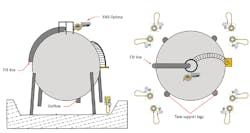
Figure 1: To cover potential leaks and head off ignition sources, gas detectors should be located on top of the tank near valves or flanges on the fill line, as well as located below the top of the dyke wall for vapors that are heavier than air, while their sensors should still be 12-18 in. above grade. Source: Lesman and Honeywell
For instance, a coverage map for an outside storage tank should indicate that detectors should be located close to any potential leak sources, and between those sources and any potential source of ignition at the monitored site. A detector should be located on top of the tank near valves or flanges on the fill line. They should also be located below the top of the dyke wall for vapors that are heavier than air, while their sensors should still be 12-18 in. above grade (Figure 1).
Greivell adds this scenario is general application note and shouldn't be the sole source of information in determining quantity and location for detector placement. "Consult additional resources when developing a monitoring system," he adds. "Additional information is available for developing combustible gas detection systems, such as the National Fire Protection Association's (NFPA) standards and the Instrument Society of America's ISA-RP12.13-Part II-1987 standard. Services are also available from professional safety engineering firms, and should be used when necessary."
Installation and startup
Once detector placements are determined, installation tasks such as mounting sensors and support components and pulling wires can start, such as installing a Modbus cabling pair to reach the SCADA system. This is typically followed by configurations and function checks, training and assigning system ownership, and confirming expectations with staff. Ownership consists of deciding who will conduct routine maintenance, calibration and bump performance verification, perform diagnostics and troubleshooting, and pay for detection technology over the years.
"All systems are going to work on day one, but it's important to plan for how they'll work and what they'll cost at fives years and beyond," says Greivell. "After the burn-in period, it's important to have a follow-up meeting to get all the stakeholders reengaged, identify alarm modifications if needed, such as setpoint adjustments, delays or sensor repositioning, and covering worst-case scenarios such as a defeated detection system. It's essential to identify all the little pains in the neck that can chip away at the confidence in a gas detection system. At the end of the day, this is all about physics and chemistry. However, when we ask what a client is trying to protect and what gas they need to detect, we may find out they're only ejecting steam once every three months, but they can still add what's needed to eliminate surprises or shocks or false alarms that might be ignored."
HART and other advances
To help users move from reactive to proactive gas detection maintenance, Greivell reports that HART and other fieldbuses and digital communication protocols can work with device management software to provide real-time diagnostics on PCs or tablets, which can use detailed fault and warning codes to better optimize troubleshooting and maintenance hours, and reduce added costs.
"Instead of the maintenance guys going out as much, a gas detection system can send data right to the control system, put useful information into users' hands, and save tens of thousands of dollars or more," adds Greivell. "However, this depends on not short-circuiting a gas detection project at the design stage, and digging as deep as possible during initial questioning. This is essential for developing a detection system that validated, trusted and believed by its users. If they don't believe it, they won't pay attention to it, and that means increased risk."
Similarly, while many gas detection methods and technologies have remained pretty much the same over time, Greivell reports there have been some crucial refinements and innovations in recent years.
"The biggest change lately has been the introduction of data processing that can crunch numbers inside devices," says Greivell. "Optical systems are also getting more affordable, such as laser diode spectroscopy (LDS) and snapshot hyperspectral IR (SHI) for virtual, real-time gas cloud imaging. They rely on faster microprocessors to process digital images from improved optics or multiple cameras, and do it more quickly and affordably, while eliminating false positives. The same goes for ultrasonic detection in high-pressure applications, where better data processing is helping reject false alarms.
"Likewise, data processing and the Internet are taking more gas detection methods that used to be just in the lab, and making them reliable enough to serve in the field. In gas detection, the goal is reliability, but people can't see most gases, so have must have instruments and alarms we can trust. Many of these new optical detection systems are hard-code calibrated, so they don't drift and know when they're not working properly. However, even though they're self-calibrating and don't need to be adjusted, it's still good to do function checks to make certain they're performing as designed within their processes."