This Control Talk column appeared in the December 2021 print edition of Control. To read more Control Talk columns click here or read the Control Talk blog here.
Greg: I am truly excited and appreciative of the involvement and achievement of leaders in process control who are coming together to create the ISA 5.9 Technical Report—a potential game changer. The PID algorithm is the most powerful tool for achieving individual loop performance as seen in the legacy of Greg Shinskey highlighted in last month’s tribute column. PID capabilities are underutilized mostly due to a lack of understanding.
Here Sigifredo Nino and I share our knowledge of PID structure and external-reset feedback (e.g., dynamic reset limit). Both of these features enable one to tune a PID to maximize load disturbance rejection as advocated by Shinskey, and still address the many other objectives and limitations. Presently, the PID is frequently detuned to deal with these situations, posing a severe, confusing burden on users, and resulting in a serious degradation in load response. The features presented here are simple to use and robust, enabling us to move on, which is greatly appreciated.
Sigifredo, what is most frequently overlooked PID feature by both systems suppliers and users?
Sigifredo: If it was not for the process variables being frequently affected by disturbances and prevented from staying at the desired value, there would be no need for feedback control.
However, along with feedback control comes the need to optimize its closed-loop response. Should it be able to reject load disturbances? Certainly. However, there are instances where process variables overshooting in response to setpoint changes isn't acceptable due to process quality or safety conditions.
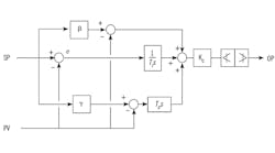
So, the question would be: optimize for a desired setpoint response OR minimize the effect of load disturbances? Well, what not enough people realize is that this question was resolved for controllers in general by Horowitz in 1963 and for PID controllers by Araki in 1984, with the formulation of the so-called Two-Degree-of-Freedom (2DOF) controller, which allows substituting OR for AND in the optimization puzzle. Figure 1 illustrates this feature as applied to the Standard PID structure.
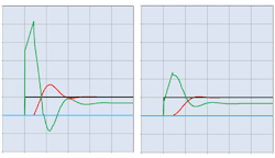
Figures 2 (left) and 3 (right) illustrate dynamic response of 2DOF-PID algorithm without (left) and with (right) filter. (Red = process variable, black = setpoint, green = controller output, blue = disturbance variable.)
Clearly, two different objectives can't be satisfied with a single degree of freedom; but the 2DOF PID allows simultaneous optimization of setpoint response AND load rejection without hindering either, as depicted in the dynamic response captured in Figures 2 and 3.
β and γ are fractions between 0 and 1. Using γ different from zero adds functionality and complexity that's beyond the scope of this short note. Therefore, to illustrate the most common benefit of the 2DOF-PID, γ is made equal to zero for the remainder of this discussion, thus providing derivative mode contribution on measurement only.
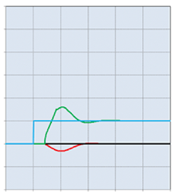
Selecting β between 0 and 1 enables a setpoint filter somewhere between a first order and a lead/lag filter, when β = 1 the controller gain is applied to the error, and when β = 0 the proportional action is applied to the measurement only. β values in between 0 and 1 allow optimization of the controlled variable response to a setpoint change. Figures 2 and 3 illustrate the result of SP filter on setpoint response, and Figure 4 shows the response to an unmeasured load disturbance is not affected at all by the SP filter.
The functionality of the 2DOF-PID presented in Figure 1, when γ is set to zero, amounts to the application of the lead/lag setpoint filter, F, shown in Equation 1:
Figure 4: Load rejection response is the same without and with filter.
This functionality does not, regrettably, appear to be a handy option for the process control practitioner, either because he/she isn't aware of it, or because the control system supplier hasn't made it available in the control blocks library. In the interest of instructing control professionals about it, this topic has been addressed in the ISA 5.9 Technical report.
Greg: Based on some testing I did with aggressive tuning for load disturbances, the rise time for a setpoint change may be faster with a γ greater than zero for a β less than 0.5, and the dead time from dead band or resolution can be less, but the brief erratic movement of the PID output may be undesirable.
The structure with no integral action is used for severely exothermic reactors that are in danger of developing a runaway point of no return. The temperature control in these reactors use a high PID gain and rate setting. Since offset and peak error is inversely proportional to PID gain, the control can be quite tight with an offset within the accuracy of the sensor. A structure without integral action is also used in batch temperature and pH control with a unidirectional response. For example, if the batch temperature and pH are being raised by the use of heating without cooling and a base reagent without an acid reagent, respectively, the batch temperature and pH can only go up. Any overshoot cannot be corrected.
My section on external-reset feedback (ERF) provides a historical perspective and the increasing awareness of expanding opportunities to readily prevent oscillations from the many problems associated with the response of the manipulated variable, and to provide more effective and safer optimization.
Pneumatic controllers used a bellows and restrictor equivalent to a filter to implement integral action through positive feedback. When electronic controllers appeared, most companies switched to using an integrator for integral action that was carried over to digital implementations of today. Some realized the value of external-reset feedback in preventing the integral mode from changing faster than the manipulated variable can respond, and stayed with integral via positive feedback or switched back to it.
ERF is turned on by switching to use a signal representing the manipulated variable instead of the PID output for the ERF filter input. When valve position readback is used, it is important that readback updates are fast and precise. The feedback signal must have the same units as the PID output and ideally be linear with the PID output. If signal characterization or split range is used, the manipulated variable signal must be reversed for the feedback to correspond with the PID output that is the signal characterizer or split range block input. Some blocks have this signal reversal capability built-in because it is needed for output initialization even if external-reset feedback is not used. The ERF filter should be momentarily initialized upon a download but if a bump still occurs, the PID can be momentarily put in the manual. ERF prevents the contribution of the integral mode from changing faster than the manipulated variable can respond but does not slow down the contribution of the proportional or derivative modes. The stopping of the integral mode is enough to suppress oscillations. The feedback of the manipulated variable must be accurate and at least as fast as the execution rate of the PID.
ERF simply being turned on without the need for PID retuning offers many opportunities. ERF can reduce oscillations from a slow response, failure, backlash or resolution in a secondary loop, valve or variable frequency drive (VFD). ERF can provide more effective override control, valve position control, RCRA pH control, split range control, and compressor surge control by quick opening and slow closing surge valves. ERF also enables dead time compensation by simply inserting a dead time block in ERF feedback signal.
3-1 Ensure a smooth response to requests (use 2DOF structure)
3-2 Eliminate overshoot in response to requests (use 2DOF structure)
3-3 Prevent action in the wrong direction when reaction to a response is accelerating reaching a point of no return (use structure with no integral action for runaway process)
3-4 Prevent action in the wrong direction when correction can only move process in one direction (use structure with no integral action for unidirectional process)
3-5 Don’t make corrections faster than colleagues can respond to (use ERF for slow secondary PID)
3-6 Eliminate unnecessary reversals of the types of correction by different colleagues (use ERF to prevent unnecessary crossings of split range point)
3-7 Enable a smooth approach to best condition with fast correction for unanticipated situation (use ERF for gradual optimization and fast getaway for abnormal conditions by valve position controller)
3-8 Delay feedback to your correction to match dead time in response (use ERF with simple dead time block inserted in feedback path set to match total loop dead time to give dead time compensation)
3-9 Reduce cycling from loose connections with colleagues (use ERF to reduce oscillations from backlash
3-10 Stop cycling from friction with colleagues (use ERF to stop oscillations from resolution limit)
