Getting Up to Smart Speed
By David W. Spitzer
The goal of optimal control is to develop a strategy to control a system (process) in the optimal or best possible manner. Academicians use mathematical techniques to prove that the optimal control strategy is in fact the best that can be done. Typically this is performed using a model of the system to mathematically prove that a given performance measure is optimized when using a particular control strategy.
One classic example of an optimal control problem is the desire by the military to get an airplane from the ground to a certain altitude in minimum time. Intuitively it would seem that the airplane should take off and ascend at maximum throttle. However, mathematical models show that the airplane should actually reduce its altitude at a certain time during its ascent in order to increase its velocity to arrive at its target altitude in the shortest possible time.
Performance measurements are subject to the same kinds of logic. Has your boss ever told you that the meeting is right now, so you had to prepare your presentation in minimum time? Have you ever worked on a project that cannot overrun, so that implementation is performed at minimum cost?
Another such performance goal is to operate your plant using a minimum amount of energy, but this performance measure is not practical, given plant complexity and mathematical resources. However, a reduced energy performance measure can be practical.
Energy Saving
Many energy-saving performance measures involve a single discipline, such as the maintenance department that finds and fixes steam leaks. However many solutions are overlooked because theyre multi-disciplinary in natureoften in conception, justification and implementation. Such is the case of the application of variable-speed drive (VSD) technologyespecially in the process industries. A VSD system that includes a drive, motor and pump is many things to many people; a final control element to an instrumentation engineer, a load to an electrical engineer, a pump to a mechanical and/or chemical engineer, and an operating expense to the accountant paying the bill. One of the major reasons that VSDs are not more widely applied in the process industries is because typically no one engineer possesses sufficient knowledge to conceive, understand and evaluate the instrumentation, electrical, hydraulic, mechanical, chemical, maintenance, operating cost and other aspects of the installation. As a result, VSD technology tends to fall between the cracks of traditional engineering disciplines.
How can you alter this syndrome and save energy? First, working with engineers trained in other disciplines is fundamental, simply because it is not common for one individual to possess all of the requisite knowledge. Second, you need to call attention to the potential of variable-speed technology. You need a champion who can gain awareness and be willing to work with others.
Show Them the Money
One important basis of awareness is to calculate the energy savings associated with an alternative VSD design in terms that management understands: M-O-N-E-Y. These calculations typically involve multidisciplinary technical information and calculations. For this reason, detailed calculations are beyond the scope of this article. (See my book, Variable Speed Drives: Principles and Applications for Energy Cost Savings, 3rd ed. ISA, 2004, for such representative calculations.)
For example, numerous applications in the process industries involve continuously pumping a liquid from one vessel into another through a control valve. In many of these applications, the transfer can be made in a more energy-efficient manner using VSD technology (Figure 1). You dont need the control valve, so its inherent problems (leakage, plugging, calibration, repair, energy loss ) are eliminated, and so the quality of control often improves due to the elimination of valve stiction and hysteresis.
Figure 1. Variable-speed drives (right) are more energy efficient than control valves (left) when pumping liquids.
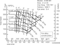
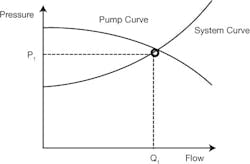
A typical pump curve describes the flow, pressure, efficiency and mechanical power requirements of the centrifugal pump at different operating conditions (Figure 2). The system curve describes the flow and pressure characteristics of the piping system without any throttling. Overlaying one on the other (Figure 3) indicates that the pump will operate at flow Q1 and pressure P1.
Figure 2. A pump curve shows flow, pressure, efficiency and mecahnical power needs at different operating conditions.
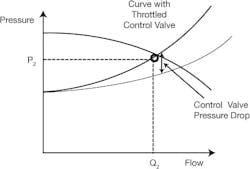
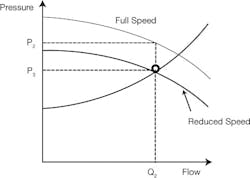
Throttling the system with a control valve increases hydraulic friction and moves the system curve to the left to maintain flow Q2 at pressure P2 (Figure 4). Note that the control valve reduces the pressure from P2 to P1 to throttle the system to operate with flow Q2. Not generating this hydraulic energy by installing a variable-speed drive that permits operation close to the system curve (Figure 5) removes the need to generate this excess hydraulic energy, and thus, operating at pressure P3 and saving electrical energy as compared to throttling using a control valve.
Figure 3. Combining the pump and system curves indicates that the pump will operate at flow Q1 and pressure P1.
The energy savings associated with this type of application are typically between 10% and 30% percent of the existing energy consumption. This concept and approximate energy savings can be illustrated by analyzing similar operating points in Figure 1. Detailed calculations should be performed to take into account the operating conditions in actual installations.
For centrifugal pumps, energy consumption varies with the cube of the pump speed, so even a modest speed reduction of, say, 10% results in energy savings of almost 27%. This can represent a significant energy cost reduction when the motor is large. In general, larger motors tend to yield large monetary savings, even though the percentage energy savings may appear small. Therefore, you should concentrate on pumps with large motors before addressing equipment with small motors.
New First
In addition, address new installations before existing installations to eliminate not only the costs associated with installing the control valve, but also the costs associated with removing it later. Note that the cost of installation for many VSD systems is often lower than that of a control valve systemeven before energy savings are consideredbecause the cost associated with the control valve (plus manifold) and the motor starter are eliminated. This is not necessarily true for large motors, where the cost of a VSD is high relative to a control valve installation.
Figure 4. Throttling increases hydraulic friction and moves the system curve to the left to maintain flow Q2 at pressure P2.
These energy savings alone are often not sufficient to justify a VSD installation. The real savings come from taking the implementation to the next level. One such application involved an air compressor, where reducing the compressor speed stopped the compressor from unloading, so it was always generating compressed air. Replacing the air compressor starter with a VSD had a simple payback (installed cost/savings) of approximately 2.7 years. Expanding the project to include process changes increased the project cost by 25%, but energy cost savings increased fourfold, and the simple payback was reduced to approximately 0.8 years!
This illustrates that replacing a starter with VSD technology can generate energy savings, but making process changes at the same time is a better investment that can save much larger amounts of energy. This is not possible in most applications, so you should first focus on applications where process changes are possible.
Figure 5. Because it runs close to the system curve, a VSD cuts the need for excess hydraulic energy and saves electricity.
Justifying the air compressor installation involved electrical, mechanical, chemical, combustion, utility, energy and other calculations in the context of plant operation. Aside from technical interactions between plant personnel representing various disciplines, it also involved detailed discussions with the compressor manufacturer regarding mechanical and heat-transfer issues inherent to the equipment itself.
Conceiving, justifying and implementing variable-speed drives often involve multi-disciplinary considerations. Failure to consider all these aspects can quite easily doom your project to failure, and cause you to miss your performance target.
David W. Spitzer is a principal in Spitzer and Boyes, LLC and can be reached at 845.623.1830 or www.spitzerandboyes.com.
