The pitfalls and promise of override strategies

An override control strategy employs two or more controllers in a configuration that allows one controller to act to maintain or regulate one process variable (the main controller) while another controller monitors a different process variable (the constraint variable) to intervene through a high or low signal selector if the constraint is exceeded. While the strategy is a simple one in principle, without adding or configuring features that prevent integral windup and avoid latency in override action, the strategy will not perform well.
When a conventional PID algorithm is used in the implementation of the strategy, integral tracking (or its equivalent) is employed to ensure that there is no integral wind-up in the non-selected controller and that it can intervene without latency when the constraint is approached or exceeded. An alternative implementation of the override strategy, made possible when filtered positive feedback is adopted to provide integral action at the controller, simplifies the implementation, and without additional provisions, provides preemptive action.
This article discusses the importance of adding a first order filter in the integral tracking signal when conventional PID is used in an override strategy and offers evidence of the benefit of using PID algorithms employing positive feedback for integral action.
Override strategy: Conventional PID with integral tracking
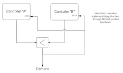
Figure 1 illustrates an override strategy using conventional PID algorithms. For the controller that is not selected, the PID integral term follows the track value. The controller output is the track value plus (typically) the controller gain times error. Unless the control error is zero, the PID output is the track value with the error dependent offset applied.
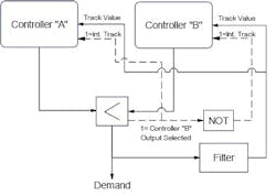
In the following discussions, the example used is that of a flow controller acting to modulate the speed of a pump drawing a commodity from a supply tank with an override controller acting on low tank level. In this application it would be a common occurrence for the flow to be higher than setpoint at least transiently while the tank level is low, both conditions demanding a reduction in pump speed. While the conditions may be momentary, when they do occur, without a filter in the tracking signal, the speed demand can be driven to zero in just several controller scans with potentially adverse consequences on plant operation.
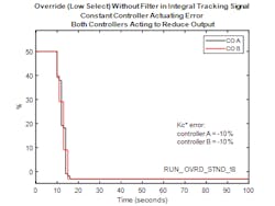
Figure 2 illustrates the behavior of the controllers in an override strategy without a filter in the tracking signal when sustained errors on both controllers are acting to reduce the demand. For clarity the output of the low select is omitted. In this case, the controller execution interval is one second.
Control Parameters:
Controller “A”
Kc=2
Ti=10 sec
Controller “B”
Kc=5
Ti=100 sec
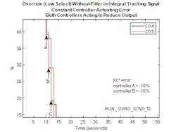
Referring to Figure 3, at instant “a” controller output “A” is less than that for controller “B” and is selected as the output at the low signal selector.
In the next scan (instant “b”), controller “A” is registered as being selected since the low selector output and status is that from the previous scan, and controller “B” is switched to the tracking mode. The output of controller “B” is calculated as the last output of the low select minus 10% and that for controller “A” calculated as its last output plus the incremental change (negative) due to integral action. At instant “b” controller output “B” is less than that for controller “A” and is selected as the output at the low signal selector.
In the next scan (instant “c”), controller “B” is registered as being selected since the low selector output and status is that from the previous scan, and controller “A” is switched to the tracking mode. The output of controller “A” is calculated as the last output of the low select minus 10% and that for controller “B” calculated as its last output plus the incremental change (negative) due to integral action. Note that since the IAT for controller “B” is longer than that for controller “A”, the incremental change at the output of controller “B” due to integral action is smaller than that for controller “A” in the previous scan. At instant “c” controller output “A” is less than that for controller “B” and is selected as the output at the low signal selector.
When a filter is applied to the tracking signal, conventional PID with integral tracking performs well in an override strategy but there are some subtleties in behavior that should be considered when the actuating error on both controllers drive the outputs in the same direction to lower the output in the case of a Low select or to raise the output in the case of a High select. Referring to Figure 4, even with a filter applied to the tracking signal, the selected output can still be subject to discontinuity when Kc*error is less in magnitude on the “fast” controller (controller “A”) than it is on the slower controller (controller “B”).
At instant “a”, for one scan, the output of controller “A” is just less than that for controller “B”, and until the next scan, is selected as the output of the low select. In the next scan, the low selector status indicates that controller “A” is selected and controller “B” output is calculated as the filter output minus 10%. Note that at this instant, the filter output is 2% higher than the output of controller “A” so that there is an 8% step in the low select output.
Between instants “a” and “b”, controller “B” output gradually reduces at the rate determined by the controller’s IAT and magnitude Kc*error (-10% in this case). Over the same interval the output of controller “A” (in tracking mode) follows the filter output minus 2% (Kc*error for controller “A”). Note that since the filter time constant is less than the IAT for controller “B”, the controller outputs are converging.
At instant “b”, for one scan, the output of controller “A” is just less than that for controller “B”, to result in the cycle repeating.
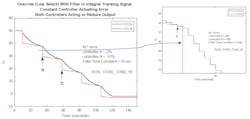
action when both controllers are acting to reduce output for a low select implementation or increase output for a high select implementation, cannot by discounted.
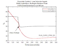
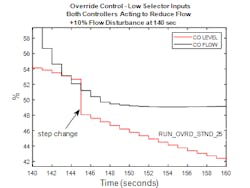
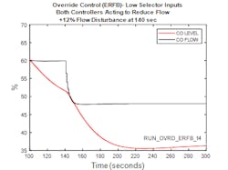
Figure 5 shows the closed loop response for the override strategy when there is an initial imbalance between tank inflow and outflow and a subsequent disturbance in tank outflow that results in the flow controller and level (override) controller both acting momentarily to reduce pump speed. Figure 6 shows the results from the same simulation but for the range 140 to 160 seconds. The conditions may seem contrived but none the less can occur in practice and serve to show the closed loop behavior of a conventional override strategy in this situation. Note that the recommended filter is included in the integral track signal.
Referring to Figure 6, at approximately 146 seconds the flow controller output is less than the level controller output and is selected by the low select. This situation lasts no longer than one scan since in the next scan the level controller matches the flow controller with a negative offset applied so that the level controller output is reselected at the low select. This results in a step in the VFD speed demand which may not be that consequential unless there is derivative action on error but is nonetheless undesirable. Note that with the filter in the tracking signal, there are no successive step changes in the VFD demand.
When in an override strategy, integral tracking is implemented without a filter, for the conditions described in the previous case, the successive handing off from one controller to the other results in a series of steps in the output of the low select until the level output is consistently lower than the output of the flow controller when the flow controller offset is positive. This is illustrated in Figure 7
A technique applied out of necessity in pneumatic controllers to obtain integral action is equivalent to using positive feedback through a first-order filter. F.G. Shinskey (internationally known as Greg Shinskey) recognized that there were benefits in applying this method of obtaining integral action in closed loop control. Among the benefits (too many to cover in this article), this method provides the opportunity to implement external-reset feedback (ERF) which can be used to advantage in an override strategy. Note that this method of obtaining integral action and the application of ERF is not universally supported by the vendors of contemporary systems but merits wide support.
When an override strategy is implemented with controllers employing filtered positive feedback for integral action (Figure 8), the implementation is simpler from a user point of view and does not suffer from the discontinuity in action when both controllers are acting to reduce demand (for a low select) or both acting to increase demand for a high select. It is beyond the scope of this article to describe the implementation of PID using filtered positive feedback and the reader is encouraged to explore the references provided at the end of this article for further information on the subject.
When an override strategy is implemented using conventional controllers with integral tracking, the discontinuity on transferring from the output of one controller to the other when both controllers are acting to reduce demand (for a low select) is due to the gain*error at the non-selected controller being less in magnitude than that at the selected controller before the transition occurs.
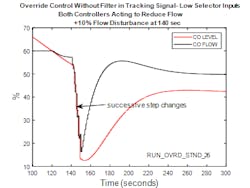
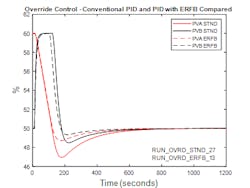
Figure 9 illustrates the closed loop response for the override strategy using external reset feedback. Absent in Figure 9 is the discontinuity evident in Figure 5 which illustrates the closed loop response when the override strategy is implemented using conventional PID controllers with integral tracking. Note that the conditions modelled in Figure 9 and Figure 5 are the same except for a slight increase in the flow disturbance in the case of the external reset feedback implementation, made to ensure that the flow and level controllers momentarily act in the same direction to confirm that there is no discontinuity in action during this condition.
Future constraint control possibilities
One of the advantages of model predictive control (MPC) in constraint control is the future prediction of a constraint violation enabling proactive action. This capability could be achieved to some degree by the use of a future value prediction for a constraint PV of an override controller. The calculation is used in batch profile control and endpoint prediction besides a full throttle setpoint response. The calculation is rather simple and easily adjusted. A dead time block is used to create an old value of the PV that when subtracted from the new PV and divided by the dead time is the rate of change of the PV. The dead time is chosen to be large enough to provide a good signal to noise ratio. This simple method introduces no dead time into the calculation seen in more traditional methods. The rate of change multiplied by a time interval to give a predicted change in PV that is then added to the new PV to create a future value PV of an override controller to enable a fast proactive reaction to prevent constraint violation. The override controller tuning would be based on the dynamics of the new PV response to the manipulated variable.
Takeaway
About the Author

Greg McMillan
Columnist
Greg McMillan retired as a senior fellow at Solutia Inc., now a subsidiary of Eastman Chemical, in 2002. He was an adjunct professor in Washington University Saint Louis’ Chemical Engineering Department 2002-04, and retired as a principal senior software developer at Emerson Automation Solutions in 2024.

Peter Morgan
Peter Morgan has 40 years experience designing and commissioning control systems for the power and process industries. He's an ISA senior member and contributing member of the ISA 5.9 PID committee.
