Charlie Cutler's Latest Ideas for Multivariable Controllers
By Charles Cutler
The most nonlinear elements in large multivariable controller models are the valve positions. All of the large-scale multivariable controllers today are assumed linear. They are based on linear differential equations that require the valve positions be linear. The valves are typically linearized using transformations that plot the flow through the valves versus the valve position. In effect, expressing the valve position as a flow linearizes the valve, since the thermodynamic properties of the system usually change linearly with flow in the region covered by the controller. The set of data used to develop the controller model is used to calculate the transforms. The transformed value becomes one more vector of numbers in the data set such that the identification program treats the transformed valve as another dependent variable in developing the controller model. Thereafter, the transform remains constant, since it is embedded in the step response models of the controller's model.
The assumption is made in developing the transforms that the upstream and downstream pressures are constant. This is an approximation that can be corrupted by a number of associated events. For example, there may be several pumps on the upstream side of the valve that have different discharge pressures and, depending on which one is in service, will change the upstream pressure. The downstream pressure can change depending on whether other flows are converging into the line or whether the pressure at the destination of the flow is changing. The destination may be a tank or a larger or smaller pipe on a pipe header. Changing either the upstream or the downstream pressure will cause the flow to change with the valve in a fixed position. Comparison of flow and valve position data from different time periods when the pressures have changed indicates the valve position calculated from the transform can be in error 40% to 50%.
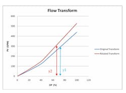
The adaptive transform overcomes the problem with the changes in the upstream and downstream pressures on a valve. At each control interval both the valve position and the flow through the valve are known. These data represent a point on the graph of the valve position versus flow. The valve position versus flow upon which the original transform was based is also shown on the graph, (see Figure 5). If the assumption is made that when the valve is closed there will be no flow, then the original transform curve can be rotated with the origin fixed through the measured point. The rotation is accomplished by taking the ratio of the measured value of the flow to the original flow at the current valve position and multiplying the ratio times the original transform. The rotated curve will have the same character as the original curve, since the relative spacing between the points stays the same. The rotated curve becomes the transform for that control interval. The derivative at the current position of the modified transform provides the change in the valve position for the change in the process variable (PV) calculated by the controller.
Figure 5: Charles Cutler, PhD, is the CEO of Cutler Technology Corporation and the developer of the MAX APC multivariable control product. He is also the developer of other multivariable control and real-time optimization algorithms. He is a member of Control's Process Automation Hall of Fame.
It is important to get the valve transformation right, since many times the valves are the most important active constraints in the optimization of a process unit. Many times the valve position on the steam to compressor turbine limits the feed to the unit. The accuracy of the transform is a factor in how far open the control valve can be moved. The standard strategy is to control the suction pressure on a compressor with the compressor speed. A better strategy is to put the PID pressure controller on manual and open the steam valve to 100%. The feed rate or some other independent variables could vary to keep the pressure in a controllable range.
The adaptation of the transform must occur outside the controller and with the controller in manual. The adaptation also requires a flow through the valve as well as the valve position. This is not an issue except for PID pressure controllers. For most applications, this is not a problem, since the flow is usually available. If a flow is not available for calculating a transform, then the PID control loop should not be broken. For flow controllers, the PV measurement of the flow can be used as the independent variable when the PID controller is in manual. The transformed value of the valve reflects the PV; however, the PV is source of the transform and is usually better understood than the valve position when analyzing the step response models.
Using the PV rather than a setpoint or a valve position as an independent variable in building a controller model is referred to as PV modeling. PV modeling has a number of advantages over using setpoints. During the testing of a process, many times one or more of the PID controllers will saturate their valves. When a valve is saturate, the dynamics of the PID controller are removed from the controller model. The model derived from the data will be in error due to the removal of these dynamics. Knowledgeable control engineers remove all the data from the analysis when a PID controller is saturated. This may reduce the data set by as much 25% to 30%. If the PV is used as the independent variable in the analysis, then all the data is good. In effect, with more data the model is improved, or the identification test can be shortened.
Using PVs as the independent variables contributes to better control by keeping the predictions correct for sticking valves. A sticking valve corrupts the controller's predictions when setpoints are used as independent variables, since it is assumed the valve moves with a setpoint change. The predictions are updated for the setpoint change. When the valve moves free again, the PV changes, but the prediction does not get updated. In effect, the prediction is corrupted two times: when a valve first sticks, and when it becomes free again. Using the PV as the independent variable in the controller model maintains the integrity of the prediction, since the PV is correct even when the valve sticks.
When PVs are independent manipulated variables in the controller, the changes in the PVs are transformed into valve position changes for execution. With the valve transforms outside the controller, they can be adapted for changes in both the upstream and downstream pressures. Obviously the PID controller's performance is affected by the changes in the valve for a constant flow.
The PID controller may become unstable if the position on the plot of flow versus valve position changes significantly. The behavior of the PID controller can adversely affect the controller model, since its behavior is implicit in the step response models of the controller. This is a further advantage of switching to a PV model, which is not effected by the behavior of the PID controllers that are put in manual.
The use of adaptive transforms and PV modeling are synergistic and have the potential to significantly improve the performance of present day multivariable controllers. Universal Process IDentification (UPID) is a commercially available product that permits the rearrangement of the independent and dependent variables in a finite impulse response model. The critical information for the PID control system is input to UPID. The tuning constants, configuration (auto, manual, cascade), the PID equation type, the brand of DCS, the valve action, the control interval, etc. are used. The first step in changing the configuration with UPID is to remove the PID controller dynamics from the model for the PID loop that is to be changed. In effect the PID controller is put into the manual mode. When the PID dynamics are removed from the model, every step response curve in the model can potentially change. This is illustrated with the following example.
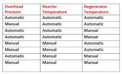
Consider the interactions between the three PID controllers on a partial burn fluid catalytic cracking unit. The PID controller for the reactor temperature manipulates the regenerated catalyst slide valve. The regenerator temperature is controlled by a PID controller that moves the air flow to the regenerator. The overhead pressure on the main fractionator is controlled by the speed of the wet gas compressor. There are eight permutations for the configuration of these three controllers, i.e. they can all be on automatic or all on manual or any combination in between.
The general equation for the number of permutations of interactions is 2 raised to the power of the number of controllers, i.e. 2 cubed is 8 for the permutations in Table 1. The number of interactions can be quite large for a complex system. The following table
Shows the eight permutations that exist for three PID controllers and the interactions between these controllers.
When a process is moved from one region of operation to another, it is not uncommon to retune some of the PID Controllers due to the nonlinearity of the control valves. During the course of a run from start-up to shutdown, the configuration of some of the PID control system is changed by switching one or more PID controllers to manual. There are a number of reasons for PID controllers to be switched to manual. Valves begin to stick or develop hysteresis, which causes the PID controllers to cycle. Many times the solution to the cycling is to put one or more of the PID controllers on manual or change the tuning of the PID controllers. The sticking valve may not be fixed until the next turnaround due to block valves not holding on the up- or downstream side of the valve, or the bypass valve around the control valve may be undersized or plugged, which may require a significant drop in feed rate while the control valve is out of service. Tightening the packing on control valves to reduce emissions has made sticking valves a common place occurrence.
The most significant problem with the current generation of multivariable controllers is the deterioration of the controllers' models with time. The ability of UPID to change the state of the independent variables in a controller's model provides insight that explains why many models deteriorate with time. The illustrations which follow clearly indicate that one major factor in the loss of the model quality and accuracy is changing the PID configuration by putting a controller on manual or retuning PID controllers. Changing the state of one key PID controller will change the step response models for all the dependent variables in the multivariable controller.
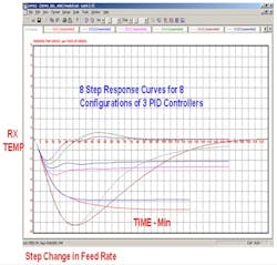
Figure 1 is plot of the step response curves for a change in the reactor temperature for a step change in the feed to the unit for the eight permutations in Table 1. For four of the permutations the reactor temperature is on control, so the temperature returns to its setpoint for a net change of zero. However, the times to reach the setpoint are spread between 25 minutes and 175 minutes, while the deviations of the temperature from setpoint, range between -2 ºF to -8 ºF degrees F. The steady-state gain for the four permutations when the reactor temperature was not on control ranged between -2 ºF and -6.8 ºF. The scale on the reactor temperature is plus or minus 9 ºF.
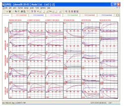
In Figure 2, the models at the top of the graph on the far left are the models from Figure 1. The other graphs are the controller's models for some of the other independent and dependent variables. As can be noted, changing the configuration of one PID controller in the model can change all the step response curves in the model.
When a process is moved from one region of operation to another, it is not uncommon to retune some of the PID controllers due to the non-linearity of the control valves. The position of the valve for a given flow is set by the pressure upstream and downstream of the valve. At a fixed flow rate, the upstream pressure is set by the pump discharge pressure and the pressure drop in the line to the valve, and the downstream pressure is determined by pressure on the vessel the flow is discharging into and the pressure drop in the line to the vessel. In effect, routine operations such as changing pumps and piping lineups can influence the performance of the PID controller due the non-linear relationship between the valve position and the flow. Good performance of a PID controller requires retuning as the relationship between the valve position and flow changes. If the PID controller's tuning is adjusted, the multivariable controller's model will not be correct, and its performance will degrade.
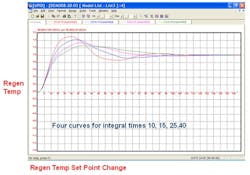
Figure3: PID Tuning changes MVC controller's model
Figure 3 illustrates the effect of changing the tuning of a PID controller on its step response model. The dependent variable is the regenerator temperature and the independent manipulated variable is the air flow to the regenerator. The four curves represent four integral times for the PID controller. The proportional and derivative tuning constants were not changed. Note that for a step change in the setpoint, the curves eventually go to the setpoint, but follow different paths in getting there.
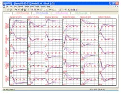
Figure 4: PID Tunning chnages MVC conoller's model
The step responses of for the variables in the neighborhood of the PID controller tuned in Figure 3 are shown in Figure 4. It is clear, the other models interact in a different way when an associated PID controller is retuned.
The economic optimization of a process that can be described by a system of linear differential equations uses all the controller's degrees of freedom at some set of constraints. Experience has shown that 20 to 30 percent of the degrees of freedom are used at valve constraints. For a present day MVC to operate at a PID valve constraint, there must be some flexibility for the PID controller to move its output or the valve will saturate. The slack in the process created by keeping a PID controller from saturating can be worth significant amounts of money.
Summary
The use of PV modeling in conjunction with updating the valve transforms in multivariable controllers represents a significant step forward in multivariable technology. PV modeling allows the more efficient use of data from testing, while the adaptive transform defines the valve constraints in a more precise way. When a control valve prevents the MPC from reaching the economic optimum, UPID can switch the associated PID controller to manual, which permits the valve to move to its optimum position. In effect, opening a limiting valve to 100% increases a unit's capacity. The dynamic components of the process—the vessels, the catalyst, the liquid levels, the piping, the furnaces—change very little with time. A majority of the MPC model problems are associated with PID configuration and tuning changes. UPID can reduce maintenance cost by minimizing the retesting of the process to solve the model problems.
XformFac
The transform rotates with each update from the DCS. The transform factor is an indication of how far off the newly rotated transform is from the original transform. In Figure B.1 below, the transform is shown for a flow valve. The flow is a PV model, so the transform has the valve position on the x-axis and flow value on the y-axis. When the valve is 60% open, the original transform shows that the flow is about 220 GPM (y1), and the rotated transform shows that the flow is about 260 GPM (y2). The transform factor for the flow transform is calculated as:

