Ibon Torrealdea Zarrabe / ENI S.A. / [email protected]
The Proposed Solution
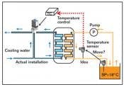
Zarabe's question: Should the temperature sensor be moved?
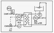
ANSWER: This is a classic case where the “human element” in your plant (your boss) makes a big difference. If he/she is over 50, just put in a CW circulating pump to fix the water flow rate, a slave TIC to eliminate upsets caused by CW temperature variation, and use the traditional cascade loop shown (Figure 2) without moving the master.
If your boss is under 40 and knowledgeable about process control software, suggest an artificial neural network control (ANNC) system. In that case, you would measure the temperatures at all points, plus any other relevant variables, and would let the ANN train itself by automatically building and continuously adopting its model to the actual dead times, time constants and nonlinearities of the process. If you want to learn about ANN, read Chapter 2.18 in the 4th edition of Volume 2 of The Instrument Engineer’s Handbook.
Béla Lipták
If you're over 50
A traditional solution to the problem is to add a CW circulating pump to fix the water flow rate, a slave TIC to eliminate upsets caused by CW temperature variation and use the traditional cascade loop shown
ANSWER: The suggestion of moving the sensor to the outlet of the exchanger to reduce dead time is a good one, though incomplete. Due to heat generated in the process, the bath temperature will be higher by a variable amount. I suggest using cascade control, where the bath temperature controller sets the exchanger outlet temperature in cascade.
Greg Shinskey/ process control consultant
ANSWER: Without knowing any numbers, it’s not possible to know the several time constants involved. And without knowing the importance of the temperature control, it’s not possible to know the monetary importance of the control.
I suggest that the temperature “from” the anodizing tank should be more representative of contents temperature than the temperature “into” the tank. If the tank temperature changes much slower than the outlet of the heat exchanger, it might be advisable to use a cascade system to make response more stable.
Use two sensors and two controllers. The “secondary loop” measures the temperature from the heat exchanger and controls the heat exchanger valve. The “primary loop” measures the temperature in the tank or exit the tank, and the output of the primary controller provides the set point to the secondary loop controller. The primary advantage of this is to isolate any changes in the temperature or pressure of the fluid controlled by the secondary loop. These may change more quickly than the primary loop temperature. The secondary loop should be considerably faster than the primary, and this is tuned for good fast response. The primary is tuned to match the slower response of the tank.
Cullen Langford, consultant / [email protected]
ANSWER: On the anodizing tank temperature control, I would not move the sensor because then the process variable to be controlled would be unknown in the future. You could get very precise control to 18 °C of the exchanger outlet, but have no idea what the tank temperature is, and that is the goal. The engineer is correct in realizing that this would remove dead time, but has made a fundamental error in not monitoring the actual process variable he is trying to control. The remedy is to put in more temperature sensors, or just manually make hourly temperature measurements in the tank and heat exchanger inlet and outlet, cooling water temp, etc., until he learns his process, and then make a decision.
Use some control charts. Use ratios of temperatures. Temperature sensors are cheap.
A bigger recirculation pump would reduce the dead time without changing the point of temperature measurement.
Morton W. Reed, Ph.D, PE / Columbus Water Works
ANSWER: The control system, within its physical limitations, acts to make the temperature at the sensor equal to the set point. Thus, if it’s desired that the temperature of the bath be controlled to the set point, then the sensor needs to be in the anodizing tank at a point of high agitation, close to the outflow pipe. Moving the sensor away will make tank temperature control more difficult.
Temperature control can be improved by using derivative control, with the derivative time constant set to the characteristic response time constant of the bath. (Expect a value between 2 minutes and 30 minutes, probably closer to 8 minutes for your process.)
Cooling water flow diversion control is used to forestall the possibility of the cooling water shut-off and freeze-up within the refrigeration system. It has little or no bearing on the control response.
The process is subject to two major sources of disturbance: the anodizing load and the cooling water temperature variation. There are other, lesser sources of disturbance, such as ambient temperature, humidity, air flow near and over the anodizing bath, etc. Assuming that the set point and process temperature are at 18 ºC, and the coolant flow through the heat exchanger is at its maximum flow value (100%) and at 14 ºC, then when the cooling water temperature drops to 6 ºC, the flow must drop by two-thirds to provide the same energy extraction from the anodizing bath via the heat exchanger. This is a very large disturbance.
The cooling flow temperature variations, if objectionable as seen by the anodizing tank temperature, can be more effectively counteracted by using cascade control. A second (cascade) proportional controller would be added, as well as a temperature sensor in the cooling water flow pipe to the process. The temperature sensor would be calibrated such that 18 ºC, the process set point temperature, represents full scale. This makes the output of the temperature sensor inversely proportional to the available cooling effort. The cooling water signal is connected to the process port of the second controller, while the output of the existing temperature controller becomes the set point of the second controller. The temperature controller needs to be reverse-acting, and the second (cascade) controller direct-acting, assuming that increased second controller output will result in more cooling water flow through the heat exchanger. The scheme just outlined depends on the set point to the temperature controller is fixed at 18 ºC. If not, another equipment item is needed to generate the set point, minus cooling water temperature signal for the cascade controller.
Otto Muller-Girard, PE, ISA Fellow / Consulting Engineer (Retired) / [email protected]
| Ask the Experts |
|
Ask The Experts |
||
|
|
|
About the Author
Béla Lipták
Columnist and Control Consultant
Béla Lipták is an automation and safety consultant and editor of the Instrument and Automation Engineers’ Handbook (IAEH).

Leaders relevant to this article:


