Measuring flare gas; Controller set points
QUESTION:
We use elbow meters to measure flare gas. What is the best measuring device, and how can we keep liquid out of the service lines? We use ABB Total Flows with drip pots on the service valves now. These are 24-in. and 20-in. lines.
Johnny Barrow, Kinder Morgan
ANSWER:
If it were a new installation, I would be inclined to use an external, non-contact type flow sensor, such as an ultrasonic one.
With an existing installation, and assuming that you can live with the measurement error of your elbow meter, I would be careful with the design of the d/p sensor lines. Your options include:
- Keeping the condensate out by locating the d/p sensor above the pressure taps and draining the legs, assuming the flare gas does not plug the lines.
- Keeping out the condensables by purging the sensor lines with nitrogen.
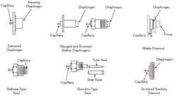
- Using extended chemical seals (See Figure 1 below). Because the diaphragms of these seals are flush with the inside surface, dead pockets are eliminated. If the gas is at high temperature, you will need to select the filling fluid for the operating temperature that you have.
Béla Lipták
FIGURE 1: EXTENDED DIAPHRAGM-TYPE CHEMICAL SEAL DESIGN VARIATIONSQUESTION:
I have two pressure controllers controlling the dp between the hydrogen and chlorine header of an electrolyzer. Both controllers have the same set point of 3.5kpa and the allowable deviation must not exceed + or - 0.2 kpa.
One controller monitors a 10-in. butterfly valve and is tuned to respond slowly to process changes. The other is controlling 6-in. rotary globe valve with fast tuning to respond quickly to process changes.
The current setting works okay if the process is stable. The big valve opens about 10% to 13%, and the small valve at 60%, but this set up does not work smoothly under upset conditions.
I have inherited this setup, and I am looking at how to set up a trim controller to achieve very tight control and a very robust controller that can respond to process changes in a more seamless manner, where the small valve will always dothe fine tuning. We noticed that when the small valve opening is between 30% and 70%, the set point is maintained very steady, but when the small valve reaches full closing or full opening, the large valve controller cannot take over smoothly.
Marwan A. Yassine
ANSWERS:
I am not clear on your description of the process: If both header pressure controllers are set at the same pressure, how are you controlling the pressure difference between them?
I assume you have two valves in parallel in each header, and not a 10-in. valve in one header and a 6-in. valve in the other.
After you have answered these questions, I can elaborate further. Right now, all I can say is that on gas pressure control, my advice is to use linear valves if the ratio of maximum to minimum valve drop is less than 2:1, and to use equal percentage valve characteristics (=%) if that ratio is higher. Therefore, if the valve pressure drop variation is low, you need linear valves.
Butterfly valves at 10% to 15% opening rotation are not linear. This you can correct by using a characterizing positioner. According to your description, the butterfly valve also appears to be oversized, because it opens only around 10%.
You should also be careful to make sure that the controller of the 6-in. valve is not faster than the positioner on that valve because that would destroy stability.
Béla Lipták
From your description, it sounds as if the valves are in parallel. A common control strategy in this situation is called “valve position control,” where the flow controller’s output controls the small valve only. A second controller is using the controller output of this first controller as its measurement. The set point of this second controller is set to 50%. The second controller adjusts the larger valve. This arrangement is commonly used in industry.
For a reference, see Greg Shinskey’s book, Process Control Systems.
John Gerry, ExperTune Inc.
We do need more inforomation The simplest way to avoid misunderstandings is to have a simplified P&ID sketch. Some major process conditions with possible range variation are needed as well, with indication of particular conditions such as quick changes (how quick?). I don’t think the valves are operating in parallel. I would have expected to have them operating in split range if they control the same stream. The fact that they are partially open simultaneously tells me I have missed some important point.
Dr. Alberto Rohr, Consultant


