Boiling water is easy as one, two, three, four

AN ANALYSIS of boiler level controls shows the importance of the interrelationships between the process, measurement instruments, and control strategy used to achieve the control objective. In short, the boiler burns fuel to convert water into steam, and makeup water is added to replace the steam (water) that leaves it.
Harold Wade suggests a few additional points be made to the three-element boiler level control figures in this article.
Operating at a high water level in the boiler can carryover water into the steam header. Operating the water level too low can damage the boiler. Neither of these conditions is desirable, so the boiler should be operated so its water level is such that neither the high nor low-level switches shut it down. The overall control objective is to replace the water that leaves the boiler in such a way that its water level remains constant.
A single-element boiler control strategy (See Figure 1 below) achieves this objective by measuring boiler level, and using a controller to manipulate the makeup water feed valve. Consequently, increasing steam demand causes more steam to leave the boiler, which lowers the water level in the boiler. The controller senses the low level (feedback), and reacts by increasing the makeup water flow to increase the level to its setpoint.
FIGURE 1: SINGLE-ELEMENT BOILER LEVEL CONTROL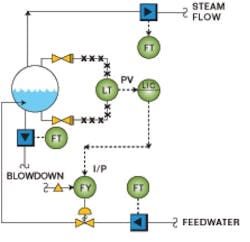
The nature of this control strategy is such that changes in the makeup water flow are initiated when the boiler level isn’t at its setpoint. Because makeup water flow will vary with demand and firing rate, the boiler level will deviate from its setpoint during normal operation. This strategy may be adequate for many boilers, especially in applications where steam demand is constant or varies slowly.
Complicating the issue is the transient inverse response of the water level in the boiler. When more fuel is burned, the water’s temperature increases and it expands, thereby raising its level. On the other hand, more water is boiled when more fuel is burned, thereby lowering the level. In actual operation, the boiler level initially increases in response to expansion followed by a drop in level due to the loss of water. Therefore, the level controller can react incorrectly to a fuel increase by initially reducing makeup water flow in response to the increasing level measurement. More sophisticated controls may be necessary to compensate for this effect.
For instance, implementing a two-element boiler control strategy by adding a cascade-makeup, water-flow control loop to the boiler level control (See Figure 2 below) can improve control by reducing level variations from setpoint and makeup water flow fluctuation. This strategy cuts the effect of disturbances in the flow loop, and allows the level loop to be tuned for better performance.
FIGURE 2: TWO-ELEMENT BOILER LEVEL CONTROL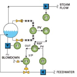
To reduce the effect of changing steam demand on boiler level, a three-element boiler control strategy can be used (See Figure 3 below). In this strategy, steam flow from the boiler is measured, and used to adjust the output of the level controller, so that a change in steam flow results in a like change in makeup water flow. This control strategy operates as feed-forward because it manipulates the makeup flow before the boiler level has time to change.
FIGURE 3: THREE-ELEMENT BOILER LEVEL CONTROL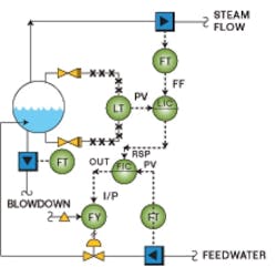
Finally, four-element boiler level control (See Figure 4 below) can be implemented by taking boiler blowdown into account.
FIGURE 4: FOUR-ELEMENT BOILER LEVEL CONTROL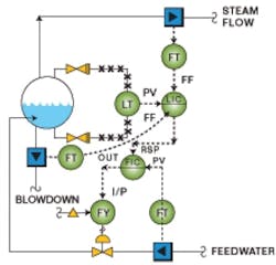
Greg Shinskey, a process control consultant from North Sandwich, N.H., says, “The magnitude of shrink-swell (inverse response) varies with the type of steam generator. In nuclear power plants, pressurized water reactors exhibit much more shrink-swell compared to boiling water reactors where large volumes of water surround the nuclear fuel.” He suggests using a non-linear filter in the controller to let the feed-forward do most of the work in pressurized water reactors (see “Taming the Shrink-Swell Dragon,” March ’04).
Fossil fuel boiler designs are more similar, so shrink-swell varies with the density difference between the water and steam. In higher pressure boilers, the density difference is less than in lower pressure boilers. Therefore, boilers operating at higher pressures generally exhibit less shrink-swell than lower pressure ones.
Alex Klemptner, lead instrumentation and control engineer at the DTE Energy Fermi 2 Nuclear Power Plant in Monroe, Mich., says, “The distributed control system that controls the reactor vessel’s water level uses single-element control for the plant startup before automatically switching to three-element control at about 20% power. The system also has a special design feature to compensate for a level swell following reactor scram (shutdown). The control system temporarily reduces the water level setpoint to supply more feedwater to the vessel. This is done to ensure that the water level stays above the emergency cooling initiation setpoint.”
Klemptner adds, “Reactor water level is the most important input into the automatic control system, so high instrument accuracy is needed. Nuclear generating stations would like to take advantage of the latest level measurement technology by using smart transmitters. However, smart transmitters aren’t qualified for nuclear applications where stringent temperature, humidity, and radiation requirements must be met.”
John O’Malley, control system engineering at Consolidated Edison (New York, N.Y.) advises, “There are additional issues that should be considered when designing drum-level controls for heat-recovery steam generators (HRSG). The HRSGs we installed use exhaust heat from a gas turbine and supplemental gas-fired duct burners to provide heat to multiple economizer, evaporator, and superheater sections. The large steam drum, rapid startup, and wide load range created difficulties maintaining drum level, so that four-element boiler water level control with metered blowdown was required.
“The differential pressure level transmitters are pressure-compensated to take the density of water and steam in the drum into account. In addition, the level setpoint is varied based upon pressure during startup."
To ensure accuracy, O'Malley uses “properly sized, insulated, heat-traced, stainless-steel impulse lines for freeze protection that’s properly installed as close as practical to the taps to reduce cost and potential leakage. In addition, the large steam drum was shown to have distinct internal waves due to rapid heat input during startup and ramping, so level transmitters are located with independent taps near the middle of the drum and at both ends. The distributed control system bases its control actions on the median of the three level transmitters or the average of two level transmitters if one transmitter is not operational.”
Sarah Parker, level products applications manager at Emerson Process Management in Chanhassen, Minn., says, “Differential pressure and displacer level transmitters are reliable and have been widely used to measure boiler level. The use of capillary tubing with diaphragm seals, as opposed to using a wet-leg differential pressure transmitter design, is primarily a matter of user preference.”
Parker cautions that level measurement systems are susceptible to accumulation of solids and should be blown down occasionally. "Susceptibility is dependent, in part, on its connections. For example, 0.5-in. tubing would be more likely to plug than a 3-in. diaphragm seal," she says. “The accuracy of these devices is affected by the water and steam density changes caused by the operating pressure and temperature. In particular, water density decreases and steam density increases as steam pressure and temperature increase. The water density alone can change by as much as 10-20% where higher pressures create greater density changes. This change impacts the level measurement, and can be significant where users want to control within 1-2 in. with a 30-in. range. Transmitters are typically calibrated to compensate for the water and steam density at the nominal operating pressure, and can compensate for pressure changes in their control systems.”
Johnathan Rowe, pressure instrument marketing manager at Invensys Foxboro in Foxboro, Mass., adds, “Multivariable transmitters can use the steam pressure measurement to calculate and compensate for water and steam density changes. In addition, error can also be introduced by ambient temperature variations of the impulse lines or capillary tubing. In typical applications, transmitter calibration is calculated assuming that the impulse lines and capillary tubing are at a fixed nominal average ambient temperature. Multivariable transmitters can be used to measure and compensate for the ambient temperature of the impulse lines or capillary tubing.”
Meanwhile, Parker reports, “There’s an increase in the application of guided-wave radar level transmitters for this application. They aren’t affected by density changes, but they are affected by the increase in dielectric constant of steam as its operating pressure increases. However, guided-wave radar level transmitters can be calibrated to compensate for nominal operating conditions, and compensation for actual operating conditions can be performed in the user’s control system.”
Implementations beyond single-element control require the measurement of feedwater, steam, and/or blowdown flow rates. “Both differential pressure, such as orifice plates, and vortex shedding flowmeters have been used in this application,” says Steve Pagano, senior product manager at ABB in Warminster, Pa. "However, the distinct trend has been towards increased application of vortex shedding flowmeters that offer high accuracy with good flow turndown within relatively short straight run requirements.
Harold Wade suggests a few additional points be made to the three-element boiler level control figures in this article.
“There is a similar trend towards vortex shedding flowmeters in steam flowmeter applications where mass flow is typically measured. Though both technologies offer pressure and/or temperature compensation in their respective multivariable transmitters, or in a separate flow computer, the trend is toward multivariable vortex shedding flowmeters that have integral pressure and/or temperature measurements. In general, it’s felt that vortex flowmeters are more forgiving than differential pressure flowmeters when measuring blowdown flow that can be subject to two-phase flow conditions.”
So there’s much more to boiler level control than simply measuring level and adjusting a feedwater valve. Improved measurements and inverse response are just a few of the influences on the effectiveness of this control loop and the ability to operate boilers in a reliable manner.
| About the Author |

