CAN solutions drive onto plant floor
Naturally, there are some key differences between automotive and industrial environments, which industrial designers need to consider when selecting and implementing CAN technology. Many non-safety-related automotive applications typically use low-data-rate CAN specifications of less than 500 kbps, rather than the faster 1 Mbps needed for many industrial designs. Also, CAN hardware used on the plant floor obviously must handle longer cable lengths than wiring in vehicles, though data rates slow as distance increases.Cable Lengths Affect CAN
Communications Speed
|
Run Length (meters) |
Signal Rate (kbps) |
REDUCING INTERFERENCE
These newer CAN devices offer advantages over conventional off-the-shelf transceiver ICs, especially in protecting against electromagnetic susceptibility (EMS), electromagnetic emissions (EME) and electrostatic discharge (ESD). High-frequency energy exposures due to long cables can hinder CAN transceivers or halt their bus communications completely in severe cases. As a differential bus, CAN already is low-noise with respect to EME. These emissions are generated whenever digital logic is switched from one state to another, such as when signals are sent via I/O pins or when drivers are turned on or off.Differential signaling, on which CAN is based, reduces noise coupling, which makes high signaling rates over twisted-pair cable possible. The optimum CAN transceiver is implemented so that current flowing in each signal line is equal but opposite in direction, resulting in a field-canceling effect that is a key to low noise emissions. Certain chip-level design techniques, if implemented correctly, will keep EME at a minimum. Some of these techniques are asynchronous switching of on-chip logic, applying slope control to reduce edges on switched signals, and matching phase and impedance of power drivers closely.Electromagnetic immunity (EMI) also must be considered when selecting a CAN transceiver. Well-designed CAN transceiver chips are implemented in a symmetrical layout with matched timing of signal transmission at 180º offset, while keeping chip internal impedances at a minimum. In addition, CAN chips are designed for robust common-mode rejection (CMR). The cause for common-mode rejection noise is the difference in the potential between grounds of sending and receiving nodes on the CAN. This noise can be picked up from fluorescent lights or switching power equipment such as power supplies and motors. Most available CAN transceivers feature a common-mode rejection range slightly above the required 2 V to +7 V for receiver inputs.By implementing these design techniques, chip manufacturers can simplify implementation of CANs physical layer functionality by eliminating the need for a common-mode choke, which makes layouts less complex and reduces bill of materials. From the ESD perspective, the high-voltage semiconductor technology employed ensures a failure voltage in excess of 4 kV.Careful design of CAN transceivers can ensure that the bus remains undisturbed if an unpowered device is connected to the bus network, while the use of built-in protection functions can guard against over-temperature and short-circuit conditions. A thermal protection circuit can trigger transmitter shutdown when junction temperatures exceed 160 ºC, while ensuring that all other IC functions continue to operate. Such protection is particularly applicable to conditions caused by a bus line short-circuiting. Using a built-in current-limiting circuit protects the transmitter output stage from damage caused by accidental short-circuit to either positive or negative supply voltage. Further protection can be provided in the form of a transmit data (TXD) dominant time-out function that prevents bus lines from being driven to a permanent dominant state; a problem that can result in the blocking of all network communication.
SYSTEM-LEVEL INTEGRATION
The availability of high-voltage, mixed-signal semiconductor technologies also allows engineers to achieve higher levels of system integration, and help them create true system on chip (SoC) ASIC solutions. For example, CAN transceiver and controller functionality can be combined in one IC to further reduce component count of CAN nodes. Higher-level integration also means that overall circuit size can be reduced, which increases space savings and opens up new possibilities that can include integrating CAN transceivers and control functionality directly into a sensor interface, actuator or motor, or adding new functions and performance without sacrificing existing board space.F
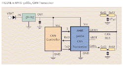
ISO 11898 standard specifications are based on a 40 m bus length with 0.3 m for stubs. This distance can be extended with a well-designed CAN transceiver. In fact, two buses can be connected by inserting AMIS-42700 one-chip CAN repeater between CAN-L and CAN-H lines. The chip has two CAN receivers and transmitters, protocol handler, and feedback suppression integrated. This one-chip CAN repeater allows designers of CAN networks simply to extend bus lengths, and allows development of a simple node for connect-disconnect applications.
The importance of integrated, miniaturized CAN interfaces is increasingly important as sensor geometries become ever smaller to fit into new applications. The added benefit of combining a CAN transceiver and controller on one chip is increased reliability, less required testing, and reducing complex component counts from two to one.
Finally, its worth noting that CANs foundation in the automotive arena gives industrial designers access to many robust and proven third-party tools and services that can support and speed development of CAN-based applications. These include tools for logically describing and configuring CAN networks at a high abstraction level, tools and services for standardizing of diagnostic data and interfaces, target code that can be used to implement a single application programming interface (API), and measurement and calibration tools and processes.
On the Physical Layer
CiA REPORTS THAT CAN defines the data-link layer and part of the physical layer in the seven-layer OSI model. ISOs standard also incorporates CANs specifications and part of physical layer, in this case, the physical signaling that includes bit encoding and decoding, or Non-Return-to-Zero (NRZ), as well as bit timing and synchronization. In the chosen NRZ bit coding, the signal level remains constant over the bit time, and just one time slot is required for the representation of a bit. The signal level can remain constant over a longer period, so measures must be taken to ensure that the maximum permissible interval between two signal edges is not exceeded. This is important for synchronization purposes. Bit stuffing is applied by inserting a complementary bit after five bits of equal value, and the receiver has to un-stuff the stuff-bits, so the original data content is processed.
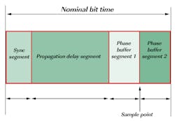
On the bit-level, which is OSIs level one/physical layer, CiA says CAN uses synchronous bit transmission. This enhances transmitting capacity, but also means that a sophisticated method of bit synchronization is required. While bit synchronization in a character-oriented transmission (asynchronous) is performed on receipt of the start bit available with each character, a synchronous transmission protocol there is just one start bit available at the beginning of a frame. To enable the receiver to correctly read the messages, continuous resynchronization is required. Phase buffer segments are therefore inserted before and after the nominal sample point within a bit interval (See Figure below).
CiA adds that CAN regulates bus access by bit-wise arbitration. The signal propagation from sender to receiver and back to the sender must be completed within one bit-time. For synchronization purposes, a further time segment, the propagation delay segment, is needed in addition to the phase buffer segment time reserved for synchronization. The propagation delay segment takes into account the signal propagation on the bus, as well as signal delays caused by transmitting and receiving nodes. Two types of synchronization are distinguished: hard synchronization at the start of a frame and resynchronization within a frame. After a hard synchronization, the bit time is restarted at the end of the sync segment. Consequently, the edge, which caused the hard synchronization, lies within the sync segment of the restarted bit time. Resynchronization shortens or lengthens the bit time, so the sample point is shifted according to the detected edge.
| About the Author |


