How best to measure multiphase flow?
This column is moderated by Béla Lipták, automation and safety consultant and editor of the Instrument and Automation Engineers' Handbook (IAEH). If you have an automation-related question for this column, write to [email protected].
Q: We need to measure an oil/water/gas multiphase flow using an orifice plate. The gas-oil ratio (GOR) is 80% and the water cut is 15%. The flowmeter is to be in the production flowline near the wellhead, upstream of the production separator. I know that this location of an orifice meter is not ideal, but our client insists. Further, the line size can't be changed because of process design criteria.
We have a separate flow control loop at this location, so highly accurate measurement isn't our concern. It can be inaccurate. Rather, I need to find a simple way to size the orifice plate as accurately as possible. In your opinion, can I calculate the size of three orifices for the three phases, and add up their areas to get the size proper size for the three-phase flow?
Considering all this, please give me your best advice.
Pooyan Ebrahimi
[email protected]
A1: In your process description, you indicated that measurement accuracy isn't important, but you didn't say what is important, what the purpose of the measurement is? I assume your purpose is just to alarm if drastic changes occur in the total flow or if the oil-gas ratio (OGR) suddenly changes. In other words, the purpose of your installation is like that of a flow alarm, and therefore it's sufficient for this sensor to act like a flow switch. In any case, I'll first make a few general comments about measuring multiphase (oil, gas, water, solids) flows from oil wells, and after that I'll answer your specific question.
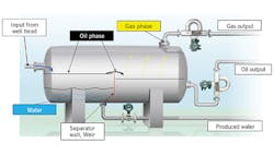
Naturally, the most accurate method of measuring multiphase flow is to first separate the components of the total stream, and only then measure the flows of the individual components leaving the separator, using high precision flowmeters like Coriolis (Figure 1). I understand your client doesn't want to do this because they want to know about any flow changes as soon as they occur. If they desire to place the flowmeter before the separator, or if the purpose of the installation is to eliminate the individual separators, then using multiphase flowmeters is a possible option.
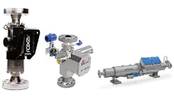
There are several multiphase meters on the market (Figure 2). They usually consist of pressure- and temperature-compensated venturi elements combined with high- or low-energy nuclear densitometers or magnetic resonance sensors. These meters can distinguish the flow rates of oil, gas and water, but suffer serious limitations. They can also reduce the amount of hardware on the topside of the well (onshore) or can be placed on the platform in offshore applications. In offshore applications, if they’re designed for high-pressure and low-temperature operation, they can also be placed in the ocean. In both cases (onshore or offshore), they can eliminate well-testing lines, which can be long and expensive, while measuring OGR or flow in real time eliminates the separation delay.
Figure 2: A selection of multiphase flowmeters from Emerson (left), Haimo (middle) and Krohne (right). These meters consist of pressure- and temperature-compensated venturi elements combined with high- or low-energy nuclear densitometers or magnetic resonance sensors.
Now, coming to your question concerning the use and sizing of orifices for approximate measurement: as you suggested, approximate sizing of these plates can be obtained by separately calculating the area requirement of the three flows (one for the oil, one for gas and one for water), and adding up these areas to arrive at the total area of the measuring orifice opening. If solids are also present, segmental plates can be considered.
If you want to increase the rangeability of this inaccurate (flow-switch quality) sensor, you can install an orifice changer with two different size plates. When using orifice changers to increase rangeability, you can have automated controls that will provide automatic switching of the differential pressure ranges that reflect the flow ranges of the two orifice plates.
Béla Lipták
[email protected]
A2: If you're going to be measuring the combined multiphase (crude, gas, water) upstream of a production separator, the following issues will affect measurement precision and repeatability:
- As the pressure in the flow line fluctuates, apparent gas flow rate will also fluctuate since the compression will be different.
- As the quantity of water and solids fluctuate the liquid (crude) flow component will also be affected.
- As the GOR of each well is different, the overall flow precision will be affected.
Based on these issues, you can have measurement errors on the order of 5% to 10% or as much as 30% to 50%. This is one reason that this sort of meter is only used to indicate or verify that there is flow in the line.
Based on your comment that precision isn't important, I would recommend that you design your measurement system as follows:
- Select a junior or senior fitting for quick change out of orifice plates as the operation runs.
- Design it to use a segmental orifice plate with a slightly higher segment profile, so gas compression effects will not be so large.
- In the calculation, add both a weep and drain hole (oversized on the plate) to prevent gas or solids from impacting the measurement of the segmental section.
- By using junior and senior flanges, you can have a set of orifice plates with a much greater rangeability, allowing for more precision.
- Most flow lines are generally between 2- and 8-in. based on expected flow rates. Therefore, when you calculate the orifice make sure that the weep and drain holes are between 1/4 in. and 1/2 in. in diameter, and take these impacts into account in your segmental orifice calculation.
- Design generally so each orifice plate can handle between 10% and 35- 40% of the total flow of similar flowlines. This way, the range of each orifice is a bit smaller, again giving more precision.
Personally, I'd choose to place a flow switch in the incoming flow line, and then measure the flow of gas, water, crude and solids at the outlet of the separator. This will not only provide more precision, but will also let users detect when issues arise with any particular well.
Alejandro (Alex) Varga
[email protected] / [email protected]
www.linkedin.com/in/alex-varga-meder


