Orifice flowmeter inaccuracies
This column is moderated by Béla Lipták, automation and safety consultant and editor of the Instrument and Automation Engineers' Handbook (IAEH). If you have an automation-related question for this column, write to [email protected].
Q: On the first page of section 2.15, “Orifices,” of your Instrument Engineer’s Handbook, Fourth Edition - Process Measurement and Analysis, Volume I, it's written that “if the bore diameter is correctly calculated, prepared and installed, the orifice can be accurate to ±0.25 to ±0.5% of actual flow."
My question is as follows: according to formula 3 of ISO 5167-1 and ignoring all other uncertainties except the discharge coefficient, C, the minimum uncertainty for mass flow rate is the same as the uncertainty of C. The latter, as per clause 5.3.3.1 of ISO 5167-1 is at minimum 0.5%.
Saeed Beheshti Maal
[email protected]
A1: A very useful question, because it shows that sometimes loop performance and component performance are confused. In the front of each chapter of my handbook, the key data for only the discussed component (in this case the orifice plate) is given, but not for the flow loop. Such key data includes uncertainty, which can also be called error or inaccuracy (but certainly not accuracy). The data for the orifice plate, as discussed in Chapter 2.15, is only for that component and assumes a calibrated plate.
This is probably also the case with the ISO statement because it assumes that ß, D, Re etc are accurately known constants and contribute zero error. With loop components, this is quite common. For example, when ABB reports its Flow-X calculator uncertainty is 0.006%, it doesn't mean the flow measurement error will only be 0.006%. In short, my advice is to read not only the front summary, but the whole chapter in my handbook because the front page summary is only for the components discussed and can be misunderstood. Actually, in future editions, I might just leave out these summaries to avoid such misunderstandings.
Now, let me elaborate about the other potential error contributions to the total uncertainty of an orifice-type flow measurement. The volumetric flow, Q, through an orifice is:
The mass flow, W, is:
Where Q is volumetric flow, C is the discharge coefficient, A is the pipe cross-sectional area, h is the pressure drop across the orifice, and ρ is the density. Now, let me mention potential error sources, which will add to the total uncertainty of the orifice-type flow measurement.
Density (ρ): The uncertainty in density (or composition) measurement is usually high (particularly in natural gas measurement), and the resulting error is additional to that of the orifice error itself. The fact that density is under the square root when measuring the mass flow is advantageous because that reduces the increase in the flow measurement error. Errors will also occur if the pressure drop exceeds 0.25 of the inlet pressure because that creates excessive density changes as the flow passes through the orifice.
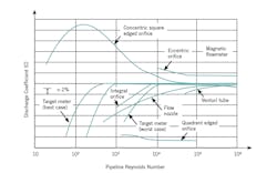
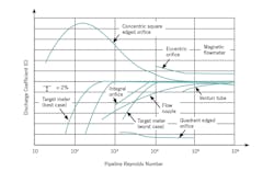
Discharge coefficient (C): The variation in C is the main contributor to the total flow measurement error because C changes are caused not only by ß ratio variations (ß ratio must stay within 0.2 and 0.65), but for many other reasons. For example, C changes as velocity profile changes due to Reynolds number variations. Figure 1 shows the relationships between discharge coefficient C and the Reynolds number for a number of head-type flow sensors, including concentric square edged, beveled, eccentric, integral and quadrant radius orifices.
Figure 1: For differential-pressure-generating flow elements, flow coefficients vary with the Reynolds number of the flow being measured.
C also changes if the location of the vena contracta varies, because it moves with the velocity of flow, and also because the downstream pressure tap is usually not at the vena contracta. Usually flange or corner taps are used in pipe sizes under 2-in., vena contracta taps are used for 6-in. or larger pipes, and pipe taps are used for sizes in between. In addition, as material builds up on the inner surface of the pipes or as corrosion or erosion reduces the sharpness of the orifice edges, the value of C also changes.
Recalibration, rangeability: Dual chamber orifice fittings allow orifice plate removal, replacement or insertion without interrupting the flow by changing orifice plates under pressure, so they eliminate unscheduled downtime. These dual-chamber devices can be operated manually or be motorized, and can reduce measurement uncertainty. They can change the flow rating (increase the rangeability) of the measurement by sliding a new plate into the flowing stream with a different ß ratio. Such fittings can also be used to replace orifices that have likewise lost the sharpness of their edges or can replace them with calibrated plates.
Transmitters: In addition to the above error sources, the measurement error of the developed pressure drop contributes further uncertainty to the flow measurement. Even newer smart transmitters with automatic span switching usually contribute about 0.1% full scale (FS) error, which being a fixed quantity, has to be multiplied by the rangeability to determine the % actual reading (AR) error at minimum flow.
The bottom line is that even newly calibrated plates with state-of-the-art transmitters will have 1% or so uncertainty; the error of an uncalibrated orifice with an analog transmitter will be no better than 2% and will grow worse over time.
Béla Lipták
[email protected]
A2: Regarding the question of orifice plate accuracy (I hate that word), it simply can't be better than the overall uncertainties of the individual components. As a starting point, the uncertainty of the discharge coefficient has to be added to the uncertainty of the measuring system, i.e. the differential pressure cell used to turn the indicated differential pressure into a flowrate. This takes the minimum uncertainty well above that stated in the Instrument Engineers' Handbook. I have to say the statement it's made is misleading in the extreme. The methodology outlined in ISO 5167-1 should be followed, and all the influential effects have to be considered.
In my experience over 40 years, I haven't found an installed orifice plate to be better than 1% even when new. The edge sharpness and pipe internal roughness change with time, and I've done independent audits on older orifice plates and found in some instances the overall uncertainty to be greater than 5%. I hope this helps answer your concern.
Dr. Richard Furness
[email protected]
A3: Perhaps you've discovered a misstatement in the Instrument Engineers’ Handbook. Also, an orifice flowmeter doesn't measure mass flow, only volumetric flow. Perhaps the statement in the ISO 5167 standard relating to mass flow is inaccurate.
Second, who cares? Using an orifice flowmeter for accurate flow measurement is foolhardy. An orifice flowmeter will never be accurate and will become less accurate over time as the sharp edge of the orifice wears. Using flange-taps is common, but the downstream flange tap is never at the location of the vena contracta, even though an orifice measurement depends on the downstream tap being located precisely at the vena contracta.
If accuracy is needed, use a positive displacement, turbine or Coriolis flowmeter. Orifice flowmeters are most often applied in flow control where accuracy isn't required, but repeatability is important.
Dick Caro
[email protected]
A4: Possibly the ± 0.25% refers to a calibrated orifice.
Ronald H. Dieck
[email protected]


