How to eliminate uncertainty, risk when performing partial stroke tests
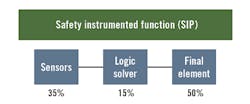
Partial stroke testing (PST) is perhaps the most maligned and misunderstood proof testing in use today in the process industries. This is due to several reasons, mostly resulting from the misapplication of the testing protocol and the equipment being used to perform the testing. When implemented correctly, PST provides an enhancement to the final element (i.e., the valve) by reducing its PFDavg contribution (50%) to the safety instrumented function (SIF) (Figure 1). The sole purpose of the test is to confirm the valve’s ability to move (not stuck in place) and its suitability for continued SIF service. A PST is necessary because a functional test is the only practical way to determine if the valve is capable of moving to a different position.
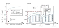
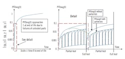
A PST is conducted periodically during the full stroke test (FST, closing the valve completely) interval, and confirms that a portion of the dangerous failure modes (as determined by its diagnostic coverage factor, typically 70%) have been functionally tested, thereby eliminating these failure possibilities. Non-covered failures continue to accumulate until a FST is performed. In most cases, the FST is assumed to provide full coverage, and the accumulated residual PFDavg is likewise eliminated (Figure 2).
When the PST is successful, appropriate safety credit can be taken for this interim proof testing with a corresponding reduction in the PFDavg of the final element. However, be advised that the PST must never interfere with the SIF or prevent its proper operation.
Figure 1: The average probability of failure on demand (PFDavg) of
the final element makes up half of the PFDavg of the safety instrumented
function (SIF).
Equipment in use
To date, most PSTs have been conducted using positioner-based devices, but this is a blatant misapplication of technology. Positioners are simplex devices developed for modulating control valves, whose movement is very small. Safety valves, on the other hand, are either fully open or fully closed, and typically move from one state to the other as quickly as possible to achieve the desired state. Positioners typically have a small flow factor (Cv of 0.6 to 0.9) due to their venting methodology, which occurs through four 1/8-in. holes in the sides of the pneumatic converter. They can't vent a valve’s diaphragm as quickly as required to satisfy the process safety time (the time window in which corrective action must be taken to avoid an undesirable event) or apply the maximum allowable spring torque to break a sticking valve free (without the possibility of over-stroking it).
Figure 2: Partial stroke tests can be done without process interruption, extending the
interval between shutdowns for full tests without compromising the safety integrity
level (SIL).
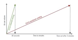
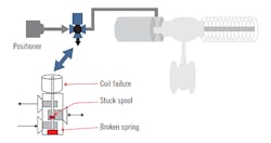
In the case of large actuators, the positioner venting alone may take many minutes to create first movement of the valve (Figure 3). To compensate for this, a simplex, non-intelligent, interposing solenoid-operated valve (SOV) is used to vent the valve’s diaphragm, and not the safety integrity level (SIL)-rated positioner. This SOV is used solely in response to a shutdown demand, and not while performing the PST. To prevent risking a spurious trip of the valve, this SOV is not tested during the PST or otherwise, and remains in an open position for an extended period of time, even though SOVs are required to be full stroked every 60 days to comply with the manufacturer’s failure data.
Numerous SOV failures are possible (Figure 4). Many failures result in the SOV not being able to close (vent the diaphragm) upon demand; and consequently, as an untested, simplex (single-channel) device, the SOV is a source of both dangerous failures and spurious trips.
In addition to the interposing, simplex SOV, positioners use a pneumatic valve-nozzle arrangement that operates independently of the positioner electronics. If the nozzle orifice is plugged (by a tiny spec of dirt or a droplet of water in the air supply), shutting off the electronics will not vent the valve’s diaphragm. This is a dangerous failure mode as venting the diaphragm (closing the valve) is critical to achieving the safe state. Regrettably, neither this dangerous failure mode, nor the untested, interposing SOV used for venting, is considered in most positioners’ product safety evaluations.
Figure 3: During a partial stroke test (PST), solenoid venting speeds valve closure. Here,
using only positioner venting, the valve didn’t move before the test timed out.
In a typical process application, the full instrument air supply (IAS) pressure applied to the valve diaphragm is 80 psig. Typical margin for the open state is 32 psig, leaving first movement to be at a pressure of 48 psig on the diaphragm. To achieve closure, the air pressure is decreased to 32 psig, leaving the remaining 32 psig as the closure margin. This means the actual pressure range for closing this valve is only 16 psig. Therefore, the pressure difference between a fully open valve (which is 48 psig, not 80 psig), and the same valve at the PST position (85% open) is nominally 2.4 psig (45.6 psig). This pressure differential is quite small (2.4 psig), and when applied to a sticking valve in a piecemeal fashion will do nothing to move the sticking valve. Consequently, the PST will fail, but the valve may not be stuck, only sticking.
A sticking valve responds much like a non-Newtonian fluid, an example being ketchup. One can tap on the ketchup bottle repeatedly, and nothing will move until you give it a good hit. However, the caveat is that you may get more ketchup than you desired, or given the simile, over-stroke the valve. Thus, it's critical to a successful PST to be able to apply maximum allowable stem torque (MAST) while preventing the over-stroking of a sticking valve that breaks free.
With a positioner, everything is fine until the valve sticks, which eventually it will. This device is not capable of applying maximum allowable torque, as it was designed to slowly vent the actuator to prevent over-stroking the sticking valve. So, expect that performing a PST with a positioner will produce false failures, due to insufficient venting, resulting in inadequate torque to free a sticking valve. This problem is not unique to larger valves, and applies equally to smaller valves as well. The venting problem is inherent in the positioner itself because of its basic design and intended purpose, which is for control and not safety. The basic intent of a PST is to simulate a process shutdown (to the extent possible), not to modulate the safety valve.
Figure 4: Solenoid vent valves speed valve response during a stroke test or emergency
shutdown, but add potential points of failure.
Adding an interposing SOV (to improve venting) only compounds the problem by introducing a single point of failure into the SIF for both safety and spurious trips. The performance of the SIF and its availability are now compromised by the reliability of the simplex (single-channel) SOV, which provides no hardware redundancy or fault tolerance—a hardware fault tolerance (HFT) of zero and is susceptible to dangerous failures as well. Either a failure of the simplex positioner or of its simplex, untested, interposing SOV will result in a dangerous failure or a spurious trip of the process.
Given the above issues, the use of travel stops (preferably pneumatic because of higher reliability) is essential to ensure that optimum PST results can be obtained, confirmed and verified, and that both false failure and over-stroking of the valve are safely eliminated.
PST testing protocol
The compelling concerns associated with conducting a PST typically are:
1. Failure of the non-redundant PST device due to lack of fault tolerance.
2. Over-stroking the valve due to sluggish response, etc., and
3. Over-torquing the valve; i.e., exceeding the maximum allowable stem torque (MAST) of a sticking valve.
Any of the above could result in a spurious trip of the process, and as with the first concern, a dangerous failure. Depending on the type of equipment being used, false PST failures are also a very likely possibility. As a result, multiple PSTs are often required to determine the actual operational status of the valve. A singe test of a sluggish or sticking valve is not conclusive, and drawing conclusions (i.e., a failed/stuck valve or inadequate safety margin) based on the results of a single PST will be misleading.
Repeating the PST multiple times, while applying maximum allowable torque (as would be the case under actual process shutdown conditions) to overcome sticking as recommended herein is highly beneficial, and will not be a concern or risk if travel-limiting stops are engaged (if installed) as they'll consequently prevent the possibility of over-stroking the valve. Travel stops will not only prevent over-stroking of valves that are sticking, but also prevent over-stroking of small valves and fast-acting valves such as those used in high-integrity pressure protection system (HIPPS) applications.
Summary and benefits of PST
To achieve consistent PST results, it's imperative to apply the maximum allowable torque to move the valve. If it does not move (after several attempts) under that scenario, then it's certainly stuck. Positioners are not capable of providing the maximum allowable torque without the use of an ancillary device (SOV), which compromises both the safety and availability of the SIF in which it is embedded.
It is also important to repeat the PST when the initial test has failed to confirm and verify the test results. In the past, this wasn't an option, but it's not perceived as problematic when pneumatic stops are installed and engaged. The stops will prevent the valve from closing past its preset PST position.
Without pneumatic stops, initiating a second or third test to confirm and verify the test result is typically considered to be a risky proposition, given that the sticking valve could break free, or a larger or fast-acting valve could travel past the desired PST position due to its momentum. These concerns are valid, but in no case can the valve travel past its preset (PST) position when pneumatic stops are installed and engaged.
Given that the PST is successful, appropriate safety credit can be taken for this interim proof testing with a corresponding reduction in the PFDavg of the final element. The primary benefits derived from implementing PST are:
1. Reducing the PFDavg over the full stroke test interval, and
2. Extending the full stroke test interval.
Both of these benefits are desirable from a safety and economic perspective; and demonstrate that PST can provide a significant improvement in the safety performance (SIL) of the final element, and consequently the SIF. However, proper implementation of PST is critical to achieving success in the field.
Use the right tool for the job
In safety-critical applications, it’s good to use a redundant device such as a high-integrity valve controller (HIVC) that is SIL 3-rated, fail-safe and fault-tolerant. When partial stroke test (PST) capability is seamlessly integrated into an HIVC redundant platform, it provides the best of both worlds. The PST device should likewise be field-tested, meet C1D2 (Zone 2) area requirements, and have been in worldwide service for several years. Several cost-effective configurations and options are available to meet the user’s specific application requirements.
If over-stroking the valve is not an option, the ultimate enhancement to the two-out-of-four voting with diagnostics (2oo4D) redundant PST architecture is the addition of pneumatic travel stops, which eliminate the possibility of over-stroking the valve. This is accomplished by combining the 2oo4D redundant PST device with a valve actuator having two sets of tandem pistons. The primary (inner) set of pistons controls the operation of the valve itself, while the secondary (outer) set functions to position and secure the pneumatic stop(s). Once in place, the pneumatic stops will prevent the valve from closing past its preset position; i.e., 85% of the fully open position. This combination completely eliminates the possibility of over-stroking a sticking valve that breaks free, a very fast-acting valve, or a larger valve that could travel past the desired PST position due to its momentum. In none of these cases can the valve move past the pneumatic stops. This combination also provides the capability to apply maximum allowable spring torque (as would be the case under shutdown conditions) to break a sticking valve free, preventing a misdiagnosed failure and premature, unnecessary maintenance.
The 2oo4D fault-tolerant architecture also provides the ability to independently test the solenoid operated valves (SOVs) prior to performing the PST to eliminate any concerns regarding the failure of the PST device, and to test (move) the pneumatic stop(s) after the PST is completed.
Redundant high-integrity valve controller
When partial stroke test (PST) capability is seamlessly integrated into a high-integrity valve controller (HIVC) redundant platform, it provides the best of both worlds.
To monitor the pressure in the primary cylinder, and provide the following capabilities:
1. Prevent over-torquing (exceeding the maximum allowable stem torque, MAST) of the ESD valve if it is stuck in place and does not break free during venting of the actuator’s primary cylinder.
2. An estimate of the remaining safety margin (pressure differential at first movement) after each subsequent PST compared to its initial calibration. If this safety margin is deemed to be insufficient, it may be necessary to service the valve to ensure its continued performance in the safety instrumented function (SIF).
It is essential to use the right tool for the job, and an HIVC with integrated PST and pneumatic stop(s) is a state-of-the-art solution to the pressing concerns of both uncertainty and risk associated with the PST of valves. It provides the full benefits of implementing PST without compromising process safety, or increasing the possibility of spurious trips and lost production.
Dr. Lawrence Beckman, president, SafePlex Systems, Houston, can be reached at [email protected].
