See ControlGlobal.com on Google+ and Walt Boyes on Google+
You can get flowmeters in insertion versions that are paddlewheel, propeller, turbine, magnetic, vortex and differential pressure sensors. Insertion flowmeters are popular in many industries, because they appear to be easy to install, inexpensive and come in technology variations that mimic full-pipe meters.But with no exceptions, insertion flowmeters are not the same as their full-pipe counterparts. In fact, there is some evidence for David W. Spitzer's claim in his book Industrial Flow Measurement that insertion flowmeters are a type all of their own.
How Does This Work?
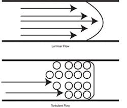
In Figure 1, you see turbulent flow and laminar flow. These are based on the concept of the Reynolds number, which is a dimensionless number relating to the ratio of viscous to inertial forces in the pipe. Laminar flow where the flow profile is straight and smooth occurs at Reynolds numbers of less than about 2500. Turbulent flow, where there are eddies, vortices and swirls in the pipe, occurs above 4500 Reynolds numbers. Transitional flow, which is neither fully laminar nor fully turbulent, occurs between about 2500 and 4500 Reynolds numbers. Laminar flow profiles are usually visualized as being bullet-nosed, while turbulent flow profiles are seen as plug flows.
Without getting too far into the math, flow studies have shown that in a pipe with a fully developed flow regime, either fully turbulent or fully laminar, the average velocity in the line can be found at a point somewhere between 1/8 and 1/10 of the way in from the side wall, depending on the flow study you read.
Insertion Paddlewheels, Propellers and Turbines
Figure 1. Turbulent flow from 4500+ Rn. Laminar flow from 0 to 2500 Rn.
There are three very similar types of insertion flowmeter that use a rotor that spins with the velocity of the fluid.The first is a paddlewheel, because the rotor is parallel to the centerline of the pipe, just like a paddlewheel steamer. Paddlewheels range from very inexpensive to inexpensive, and are designed to be disposable. The least expensive ones use polymer bearings, which go out of round and cause the rotor to wobble before the rotor shaft cuts through a bearing and goes downstream. The best use jeweled bearings and ceramic shafts so that they have much more longevity and less drag.
The spinning of the rotor is sensed by either a magnetic pickup that generates a sine wave the frequency of which is proportional to velocity, or a Hall effect sensor that generates a proportional square wave.
Read Also: Going with the Flow
The advantage of the magnetic pickup is that it generates the sine wave without additional power. The advantage of the Hall effect sensor is that it does not cause "stiction" (the momentary friction stop when the rotor sees the magnetic pickup's magnet). Hall effect sensors generally are able to read lower flow rates and are more accurate at lower flow rates as well.
Paddlewheel flow sensors are designed to be easily inserted into a small hole cut into the pipe using a custom fitting. Some paddlewheel sensors can be inserted into the pipe using a hot tap assembly, which allows the sensor to be inserted and retracted without shutting down the flow or relieving the pressure in the pipe.
Propeller meters use a prop shaped very much like an outboard motor's propeller and are generally connected to a mechanical or electromechanical totalizer with a cable very much like a speedometer cable. In fact, there is a legend that one very large manufacturer of propeller meters made a very inexpensive lifetime buy of Ford Pinto speedometer cables and used them for years. Some more modern propeller meters use embedded magnets and either magnetic pickups or Hall effect sensors. Like paddlewheels, propeller meters have a pulse output that is proportional to the average velocity in the pipe. Because propeller meter rotors are large and located at the centerline of the pipe, they are likely to be quite accurate, and even insertion propeller meters have been certified for billing purposes for decades.
Propeller meters, because their prop is significantly larger than a paddlewheel, are inserted using a flange that mounts into the upright member of a tee fitting.
Turbine meters come in both electronic and electromechanical styles, but the only insertion turbine flowmeters are electronic. They, like paddlewheels, use either a mag pickup or a Hall effect sensor to produce an output pulse that is proportional to the velocity of the fluid. Like paddlewheels, they must be inserted to the "average velocity point" that exists somewhere between 1/8 and 1/10 of the inside diameter away from the pipe wall.
Most insertion turbine meters have very small rotors, so they can be inserted through a small diameter fitting or through a small diameter hot tap assembly. Sometimes, especially in the municipal water industry, this is called a "corporation cock assembly," but it is essentially the same thing—a way of inserting a probe through a valve and still maintaining the pressure in the pipe without leaks. At least one vendor uses a larger turbine rotor and claims significantly better accuracy, especially at low flow rates. Your mileage may vary.
Propeller meters are almost always used for water service, either in potable water systems or in irrigation systems.
Paddlewheels and insertion turbines can be used in a variety of applications, with materials of construction varying based on the requirements of the applications, such as acids, bases, and hot or cold fluids.
Electronic paddlewheels and turbines can be set up to be bidirectional using quadrature detectors, which enable the signal to indicate either forward or reverse flow as well as flow rate. These are often used in HVAC applications where chill water and hot water flow through the same lines depending on the season.
The signal from the paddlewheel or turbine or electronic propeller meter is sent to a transmitter, which uses the pulse (or frequency) output to display flow rate and increment a totalizer (usually electronic). These transmitters generally have a pulse output, an analog output (usually 4-20 mADC), and often have one or two programmable relay contact closure outputs. These can be used as flow alarms, as diagnostic alarms or as a rudimentary dead-band controller.
Insertion dP Flowmeters
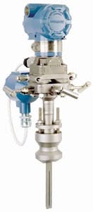
The most commonly used flow sensor in the world continues to be the differential pressure transmitter connected to a primary device such as an orifice plate or Venturi tube. In its insertion incarnation, the differential pressure sensor is connected to a pitot tube inserted in the flow stream, and just as a pitot tube measures velocity on the outside hull of an aircraft, the pitot tube measures the velocity in the fluid flowing in the pipe.
Several companies now manufacture multiple-point pitot sensors. These sensors are mounted perpendicular to the diameter of the pipe, from one side wall to the other, and have several pitot ports located along the length of the sensor. The way these multiple-port pitot tube flowmeters work is that the differential pressure sensed is the average of all the differentials across the pipe—producing an output signal that very closely corresponds to the average velocity in the pipe. This way, the sensor is connected to a standard differential pressure transmitter, not several of them.
An advantage of multiple-port pitot tube flowmeters is that they can be calibrated to take very disturbed flow profiles, such as that in a 90° elbow, into account and can, therefore, be used in locations where no other flowmeter either can be used or can be used accurately. Nearly all manufacturers of multiple-port pitot flowmeters can produce these custom calibrations, and they are relatively economical.
Insertion Mag Meters
Insertion magnetic flowmeters are not the same as spool-piece magnetic flowmeters, even though they share the operation of Faraday's law. In a spool-piece magnetic flowmeter, the design geometry of the coils and the electrodes cause the signal output on the electrodes to be directly proportional to the average velocity in the pipe. Insertion mag meters use the same concept of "average velocity point" that the insertion paddlewheel does and are about as accurate. Where a spool-piece magnetic flowmeter can reliably be assumed to be close to 0.5% of rate accuracy, an insertion mag meter can often be 10% or 15% of rate, or worse.
Like everything, however, there is an exception. One vendor realized that if it replaced the pitot port on a multiple-port pitot sensor with ganged magnetic velocity sensors, it could make a multiple-sensor insertion mag meter that could be calibrated to be remarkably accurate, and, like the multiple-port pitot meter, be equipped with custom calibrations to account for highly perturbed flow profiles. These devices have been shown to be capable of 1% of rate in some applications.
Insertion Vortex and Target Meters
Insertion vortex-shedding flowmeters have proponents, and several vendors supply them. These devices have accuracies similar to insertion turbine sensors, but have fewer moving parts and no rotor. This makes them the clear favorite from a maintenance point of view.
There is also at least one vendor of shaped-target flowmeters that uses a custom- shaped target in the flow stream that is connected to a strain gauge bridge.
Designing and Specifying Insertion Flowmeters
Basically, if you can use a spool-piece flowmeter for your application, do it. They are inherently more accurate and have volumetric calibrations instead of just velocity calibrations. Generally, you will use insertion flowmeters where you cannot use a spool-piece, either for safety or expense reasons. Insertion paddlewheel flowmeters are often used in industrial water treatment applications and for driving chemical feed systems. Even the multiple-port pitot tube flowmeters are less inherently accurate or repeatable than a spool-piece flowmeter, regardless of technology.
Accuracy and Calibration
The accuracy problem with insertion flowmeters is that they are inserted into an uncalibrated spool section of pipe or even an elbow. The "average velocity point" theory is dependent on a fully developed flow profile, with no swirling or distortion.
While it is almost certain that insertion meters will not be "accurate," they can be quite repeatable, which, in a flow control loop application may be all you need. Driving a chemical metering system, for example, requires repeatability more than absolute accuracy.
When you design an application for an insertion meter, you need to be much more careful of piping issues, such as elbows, valves, thermowells and other obstructions upstream of the sensor, than if you were using a calibrated spool-piece meter. You need to be aware that the accuracy is going to be substantially less than you can get otherwise. The reason to use an insertion meter is nearly always that it was not designed into the piping originally, or it is being used as a low-cost sensor or a low-cost replacement for an original meter.
For these applications, the insertion flowmeter can be a useful tool in the design engineer's tool bag.
About the Author
Walt Boyes
Walt Boyes

Leaders relevant to this article:


