By Béla Lipták, PE, CONTROL Columnist
In the first three parts of this series, I discussed the individual loops used to control the distillation process. Now it is time to discuss the overall control strategies for the complete column, treated as a single unit operation. Here, the individual variables will only be treated as constraints and so long as their values are within acceptable limits, the column will be optimized to maximize production, minimize operating cost or meet other optimization criteria.
To optimize the profitability of the operation, one must know what product composition variations are acceptable and what the relative economic values of the product streams are and the cost of energy used in the separation. In addition to keeping the top and bottom product compositions within specification, the column must be stable and operate against equipment constraints.
Plant economics can change because under certain conditions, energy savings may be the overriding concern, while at other times the key criteria may be product recovery. It is also important to minimize the disturbances propagated to downstream units and rework or recycle of off-spec products, and to maximize the consistency of product quality. Thus, the optimization objectives of a column can often change with time.
Constant Separation
Under constant separation, the energy-to-feed ratio of the column is constant. This reduces the number of degrees of freedom, because for each concentration of the key component in the distillate, only one corresponding concentration exists in the bottoms. Therefore, if the feed composition is constant, the holding of one product concentration constant, fixes both.
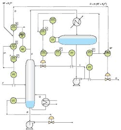
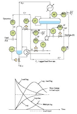
Figure 1 below shows a feed-forward control system for constant separation in which distillate is the manipulated variable. The control system is so adjusted that when the design or normal distillate-to-feed ratio is required, the output of the trim analyzer controller ARC is 50%. If the gain of the multiplier (FY) is set at 2, its output (the set point of the distillate FRC) tracks the column feed rate if the distillate-to-feed ratio is as designed.
FIGURE 1The block labeled “dynamics” in Figure 1 provides dynamic correction by modifying the transient response to match the actual time response of the distillate to a change in feed rate. This block is usually a combination of a dead time and a lead-lag function in series. The dynamic correction is active only during load changes, while in the steady state, its output equals its input. The characteristics of the more common dynamic compensators are shown at the bottom of Figure 1.
Recovery
If one product, such as the distillate (D), is worth much more than the other, the control system can be designed to maximize the production of this more valuable stream. If only the composition of the distillate product needs to be controlled, the bottoms product composition can be left uncontrolled. If maximum distillate recovery is desired, the distillate flow can be calculated on the basis of material balance.
If energy is not free, the distillate flow, which will correspond to maximum recovery, is a linear function of the feed flow: If the heat required by the reboiler is not free, the distillate flow, which will correspond to maximum recovery, is ,
Where:
D = distillate rate
F = feed rate
K = adjustable coefficient
K2 = 1 – K
K3 = adjustable coefficient
m = feedback trim
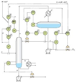
Figure 2 below describes the controls for a maximum distillate recovery system, where the boil-up energy is free and this heat input rate is constant. As was shown earlier, in this case the distillate flow, which will correspond to maximum recovery, is a nonlinear function of the feed rate. In this control system, a summing block (which can be in software or hardware: FY-1) applies the coefficients K and K2 and computes (KF + K2F2).
FIGURE 2The trimming feedback (m) provided by the composition overhead controller (ARC-2) usually has a range of 0.35 to 0.65. This is the output signal range of the feedback controller (ARC-2). The adjustable coefficients can be calculated K and K2 with reasonable accuracy and adjusted on-line. In order to increase the response of the control system (minimize the effect of accumulator lag), the reflux flow controller (FIC) set point is directly adjusted by the distillate flow measurement.
Composition Control of Both Products
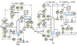
Constant separation control cannot be used if the feed composition is unpredictable, and if the composition of both products needs to be controlled. In such an installation, the overhead composition controller (ARC) can be assigned to control the material balance and the bottoms composition controller can be used to manipulate the energy balance (V) of the column (left of Figure 3 below).
The main benefit of dual composition control is minimized energy consumption, while the main limitations are the severe interactions between the composition loops. In a feed-forward dual composition control system, the distillate composition can be maintained by manipulating the distillate flow according to the relationship:
In order to control the composition of the bottom product, material balance manipulation cannot be used, because it is already being manipulated to control the overhead composition. If one also attempted to throttle another product stream, this would conflict with the material balance and would change the accumulation in the column.
Consequently, the bottoms composition (x) has to be controlled by manipulating the energy balance of the column by throttling the boil-up rate (V = Q). The relationship between separation (S) and the ratio of boil-up to feed (V/F), can be expressed as , where a and b are functions of the relative volatility, the number of trays, the feed composition and the minimum V/F. The boil-up rate (V) can be calculated by the following equation , where [V/F] is the desired boil-up to feed ratio.
The dynamic characteristics of the column (dead times and time constants) are compensated by the FY element identified as “dynamics” in Figure 3. If correctly tuned, it will guarantee that the feed-forward manipulations will arrive at the controlled variables (D and V) at the right time and in the right amounts. At the bottom of Figure 3, the characteristics of a number of dynamic compensators are described.
Two Products with Interaction
Interaction is unavoidable between the material and energy balances in a distillation
column. The severity of this interaction is a function of feed composition, product specification and the pairing of the selected manipulated and controlled variables.
Severe interaction is likely to occur when the composition controllers of both products are configured to manipulate the energy balance of the column. An example of such a case is when reflux flow (L) and steam flow (Q) are manipulated by the two product composition controllers. In such a case, the heat input is while the reflux rate is L = K1Q – K2F. Therefore, both product flow rates are dependent on energy balance terms.
In this configuration, if one composition controller is increasing the heat input to the reboiler, this action will force the other composition controller to increase reflux flow to withdraw that increased heat. Therefore, without decoupling, the two composition controllers “fight” each other, and severe interaction will occur.
In the decoupling equations given above for Q and L, the values of k1, k2 and K are determined by using the actual process values of [L/F], [V/F]min, and [V/F]. By implementing the decoupling equation L = K1Q – K2F, the tendency of a change in heat input at the bottom of the column, causing an upset in the composition at the other end, will be minimized (right of Figure 3), because the decoupling loop adjusts the reflux flow independently.
While the top composition loop is decoupled, the heat input is still coupled to reflux, because a change in reflux will still cause the bottom temperature controller to adjust steam flow. This type of half-decoupling, therefore, does not eliminate interaction completely, but is enough to reduce the interaction approximately twenty-fold.
The limitations of decoupling include that overrides can drive the loops to saturation when constraints are encountered. In some distillation columns, small measurement errors also can completely destroy the operation of such decoupling systems. Since the decoupler gain settings (k1, k2 and K) depend on the process gains, and because process gains change with variations in feed rate, product specifications and column characteristics, these systems require constant attention and retuning. Such adjustments are beyond the capability of the average plant operating personnel and require the availability of sophisticated column models.
The difficulties associated with decoupling justify the detailed evaluation of column behavior. As was discussed in the first article of this series, an important tool of such an evaluation is the calculation of the relative gains of the various configurations. One general rule worth remembering is that the composition controller for the component with the shorter residence time should adjust vapor flow, and the composition controller for the component with the longer residence time should adjust the liquid/vapor ratio.
| About the Author |
About the Author
Béla Lipták
Columnist and Control Consultant
Béla Lipták is an automation and safety consultant and editor of the Instrument and Automation Engineers’ Handbook (IAEH).


