Vortex flowmeters and low-pressure steam applications
Q: May I have your advice for a formula sheet to size a vortex flowmeter? Is the data below enough for specification and is there a specification form I should use? Could you advise if the use of vortex flowmeter is the best selection for a low-pressure steam application?
Steam flowmeter
Normal flow: 2,200 kg/hr
Pressure: 3 barg
Temperature: 144 °C
Parninggo Butar
instrument engineer in Indonesia
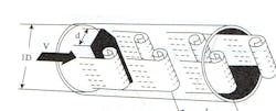
A1: Before answering your question, I'd like to tell you how the theory of vortex shedding was born, and share the role that fishing and Saint Christopher played in its discovery. An observant young man named Tódor Kármán was fishing at a spring in Budapest, Hungary, and noticed vortices forming behind bluff-shaped rocks, but not behind streamlined ones.
He was fishing at the same spot one day after a rain and noticed the water was running faster, but the distance between the vortices shedding from alternate sides of his bluff rock were the same. This was because the change in the water's speed changed only the number of vortices, but not the distance between them.
Later, his class of engineering students took a trip from Budapest to Bologna and visited the great museums. While the other students just walked by a 14th century painting, the observant Tódor stopped. On the painting, a giant rendering of St. Christopher with a bluff-shaped walking cane in his hand was carrying little Jesus across a river. Tódor whispered: "The fish jump at equal distances and on alternate sides."
It took Tódor some years to figured out that the distance between vortices has to do with the size of the bluff body. It was then that a key unit of traveling in air or water, the ratio of inertial and viscous forces, was discovered.
At the age 34, as a soldier in the Austro-Hungarian army in World War I, he used that knowledge to design an early helicopter. Later, he advanced rocket science and became the first director of NASA's space exploration laboratory, among many others. He measured the thickness of the earth's atmosphere and after—besides being referred to as one of the "Martians”—he received the U.S.'s first National Medal of Science in 1962.
Béla Lipták
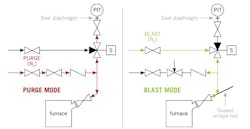
Q: I'm process engineer working at a visbreaking unit at Pak Arab Refinery. Visbreaking heaters reduce the viscosity of the bottom from a vacuum column through thermal cracking. The fuel for the heaters is either fuel gas or fuel oil. During the past two years, our high-pressure trips were falsely actuated. We found that this was caused by the pressure transmitter sensing lines being plugged with soot and smoke particles. Now, we're considering a modification of its design. Please suggest some designs of a purging system that would be suited to keep our impulse lines open.
Muhammad Usman Saeed
process engineer, Pak Arab Refinery Ltd.
Béla Lipták
A2: I don't know of any purging standard, but some users and contractors will have their own. Purge gas supply pressure must be higher than the maximum pressure for which the system was designed. A check valve on the purge supply line is required. A "purge" rotameter with an inlet-end needle valve is commonly used. To purge air flow, something around 250 cm3/min is a common range. Adjust the flow to 50% with the needle valve. Because the purge pressure drop is across the needle valve, the flow is nearly constant despite pressure changes. It depends on the actual pressures.
Air is commonly used unless there's some requirement for an inert gas such as nitrogen. In rare problem situations, we've used a second, small, liquid solvent purge to wash the dip tube. This must be added close to the process connection, and from that point on the impulse line, it must slope downwards to the process.
Cullen Langford
consultant
A3: Use a purge rotameter with service air. If service air isn't dry enough, use instrument air. Still, you'll have to schedule periodic blowing of the impulse lines. You can always implement a semi-automatic blowing system using solenoids, but the logic must be carefully written because you can have low- or high-pressure trips if it’s a balanced-draft furnace
Sigifredo Nino
process control consultant
A4: I remember an application in the alumina refining industry where we measured the line pressure of the slurry line from the digester to atmospheric flash tanks. This slurry used to plug the tapping points. To keep the tapping points clean, we used high-pressure water (slightly above the operating pressure) to wash away the slurry buildup.
In your application, you could use nitrogen purge (inert gas) to achieve a similar cleaning action of your impulse lines. Please be aware that the measured pressure will be slightly higher than the actual value, so you'll have to compensate for it.
Raj Binney
control engineer


