After a thorough analysis, a control system upgrade provided the means to tame the shrink-swell dragon taking up residence in the steam generators of Maanshan II, a 950-MW pressurized-water reactor nuclear power plant in southern Taiwan. Maanshan II's design is complex, with three parallel steam generators, each with its own feedwater control system, and three feedwater pumps connected through a common header.
Shrink-Swell Effects
The shrink-swell phenomenon is caused by variations in the vapor-liquid ratio in the evaporating section of a boiler or steam generator (SG). In the interest of accuracy, water level is measured over a narrow range at the water surface, although most of the water inventory lies below the taps of the narrow-range (NR) transmitter. It is much like measuring the tip of an iceberg.
When steam is not being generated, the evaporating section is completely flooded with water. As boiling begins, however, vapor bubbles start to occupy some of the space, lifting water into the range of the NR transmitter, indicating a higher level, even though the water inventory may actually be decreasing. As power generation increases, the vapor volume in the evaporating section will increase proportionately, leaving a progressively lower inventory of water. This can be observed in a lower measurement of wide-range (WR) level, which senses the most of the water inventory. Because the WR measurement is less accurate than the NR measurement, and must change with power generation for the same NR lever, it is not normally used for control.
Read Also: Improving PID Controller Performance
The problems caused by shrink and swell are dynamic as well. When the amount of steam being withdrawn from the SG is suddenly increased, its pressure starts to fall until more heat can be transferred to the water. This drop in static pressure causes the vapor bubbles to expand, lifting more water into the NR area. The swelling-level effect causes the level controller (LC) to reduce feedwater flow at a time when a higher flow is required to match the higher demand for steam. The opposite effect "shrinking level" follows a decrease in steam withdrawal.
In a three-element (3E) feedwater control system, the steam-flow signal is used in a feedforward manner to set the feedwater flow controller (FC) to the same flow. However, in biasing the feedforward calculation, the LC acts counter to the direction of the load change. Thus the LC counteracts the swell effect by reducing flow while the load is increasing, or the shrinking effect by raising flow while the load is decreasing. This action has value because water inventory must be reduced at higher power and increased at lower power.
A single-element (1E) feedwater control system however, has neither a steam nor feedwater flowmeter, but relies on the NR controller to position the feedwater regulating valve (FRV) directly. Without the help of the steam-flow input, the LC will initially drive the FRV in the wrong direction on a change in load.
A second, and perhaps even worse control consequence of shrink and swell is its inverse response, especially at lower power when feedwater temperature is much lower than that of the steam being generated. If the feedwater flow is suddenly increased by the LC, it tends to collapse some of the steam bubbles, causing the NR level to fall, while increasing water inventory at the same time.
Although this reversal of direction of the NR level is temporary, the delay between the opening of the FRV and the eventual rise in NR level could be as long as a minute or more, making the level very difficult to control. Inverse response is quite similar to dead time in its delaying effect on the control loop2.
Read Also: 35 Years of Extraordinary PID Innovations
In Unit I of the Maanshan plant, the NR level under 1E control was observed at one point to be cycling with a period of about seven minutes, with the WR signal cycling at the same period, but leading the NR signal by 1.5-2 minutes. The amplitude of the WR cycle in percent of scale was about 1/5 that of the NR cycle in percent of scale. Could the WR signal be added to the NR controller" something like how a derivative (lead) is added to a PI controller" to make a PID?
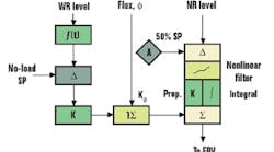
This scheme was added as shown to the 1E system of Maanshan Unit II. Although published information refers to the WR level input as "feedforward,"2 actually it is not" it is a proportional feedback input, because changing the FRV position changes WR level. In essence, this scheme combines proportional control of WR level with PI control of NR level.
The load change was simulated from a steady state at zero deviation by placing the LC in Manual, stepping its output by an acceptable increment, and then transferring immediately back to Auto. This placed the controller output apart from the steady plant load by that increment, requiring it to integrate back to its last steady-state value, which matched the load. An increment in controller output in one direction is equivalent to an increment of the same size in load in the other direction.
Take careful note though. To test a liquid-level loop by stepping its set point is a mistake. First, most level loops operate at constant set point all the time, so set-point response is meaningless. Secondly, the steady-state output of a level controller matches the load and is not a function of its set point. Following a step in set point, the LC output will return to its previous steady-state value. This does not require the controller to integrate, as a load change does, and produces a response curve having an integrated error of zero, and hence an area overshoot of 100%. By contrast, the overshoot resulting from a load change is determined by the integral setting of the controller.
Read Also: PID World Tour--The Final Performance
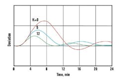
From the load change simulation came the conclusion that the WR gain K should be set to 5, because that was the amplitude ratio of the NR to WR cycles observed in Unit I. This had an immediate stabilizing effect on NR level. As a result of this success, K was then increased to 8, 10 and finally 12, where it remained. This reduced the loop oscillation period by a factor of two, and allowed a commensurate 4-min. reduction in the integral time of the NR controller. This was the fastest and most stable 1E response ever observed at the plant. The NR proportional band was left unchanged at 60%.
Differential-pressure Control
Feedwater flow is a product of FRV opening and the square-root of its pressure drop dp. The pressure drop in this plant is regulated by manipulating the speed of the feedwater pumps. This loop is especially important to 1E control, because any variation in valve dp changes feedwater flow, requiring the NR LC to operate the valve by integrating the resulting level deviation. Therefore the dp controller should be tightly tuned. At Maanshan II its proportional band was reduced to 50%, where a lightly-damped oscillation broke out; it was then increased to 75% and left there.
The dp loop gain was expected to change with the number of pumps n being manipulated by the controller, and so the proportional band of the controller was multiplied by n. However, this left the loop overdamped with three pumps running, indicating this was overly cautious. The expected interaction between the dp controller and the three parallel feedwater flow controllers, however, did not create any problems.
The set point of the dp controller at Unit II was programmed to be proportional to plant power generation. This conserves pump horsepower, which varies directly with the product of feedwater flow and FRV dp. A properly executed program keeps the steady-state opening of the FRV approximately constant with generated power.
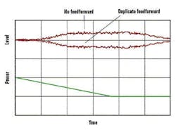
Figure 3: Level fell during power rampdown, indicating too much feedforward.
Figure 1 shows a neutron flux signal used as a feedforward input to the 1E control system. This was implemented in Unit II, along with the dp set-point program. During a rampdown from 14 to 7 power, the NR level was driven down about 12%, where it stayed until the ramp was ended. A constant deviation during a load ramp is common to feedback loops without feedforward (Figure 3), because the controller must integrate a constant deviation in order to ramp its output. However, without feedforward, the level should have risen during the rampdown, as more water was being delivered to the SG than the falling load required. So the low level during the ramp indicated that too much feedforward was actually being applied.The gain K of the flux feedforward input should be set at m/, where m is the output of the NR level controller. Accordingly, the LC output at the initial and final steady-states were compared, and found to be the same! The reason for this is the programming of dp with power"all of the load change was transferred from the FRV to the dp loop. In other words, the reduction in feedwater flow required to match the plant load was achieved by reducing the dp across the valve, instead of closing it. As a result, the feedforward input from neutron flux actually duplicated what the dp set-point program had accomplished.
To eliminate the duplication, K was set to zero. It can be seen that the two responses in Figure 3 are mirror images of each other. Therefore, the proper amount of feedforward achieved by the set-point program of the dp controller, left the level constant. Because the LC output is the same before and after the ramp, integrated error with K set to zero is also zero.
Nonlinear Filters
To reduce the negative effect of shrink and swell accompanying every load change, nonlinear filters were applied to the deviation of both the 1E and 3E-level controllers. They consist of three zones shown in Figure 1: the center zone has a width of ±z and a gain of kz, and the outside zones have a gain of 1.0. For the level controllers at Maanshan II, z = ±3.0% and kz = 0.4. Minor upsets produced level variations of less than ±3 %t, where kz diminishes the effects of these variations on feedwater flow, allowing the feedforward signals to do their work. Any major upset that drives the level deviation beyond 3% promotes a greater driving force to return the level within the low-gain zone where damping is heavier.
Figure 4: When the controller was left in
manual too long, an offset cycle developed.
However, the proportional band of the level controllers must be tuned for stable response to a larger upset. Originally, the 3E LC was set for 60% proportional band, which was stable for deviations within the low-gain zone. Eventually, a larger upset caused the deviation to exceed 3% on both sides of set point, promoting an expanding triangular cycle. This behavior is shown in Figure 4. Increasing the proportional band to 100% dampened the cycle and eliminated any recurrence.
At one point, stability of the 1E loop was tested by placing the LC in Manual and stepping its output upward. However, the LC was left in Manual until the level exceeded the low-gain zone, and then returned to Auto. The higher gain of the level controller in this zone quickly turned the level back toward set point, but started a proportional cycle above set point. Integral action brought the cycle progressively back toward set point, and after the low-gain zone was re-entered, it dampened. This response is compared to a simple step load change in Figure 5. It did not require a re-tuning of the level controller. As a result of the WR proportional loop's help, the proportional band of the 1E LC was left at 60%, compared to the 100% setting required for the 3E LC.
Conclusion
Feedwater control must be both stable and responsive across the entire plant load. This is particularly problematic at loads below the range of steam and feedwater flowmeters, where single-element level control must be used. With the assistance of proportional feedback from a WR level measurement, the effect of inverse response was mitigated and the single-element loop response time was reduced by a factor of two.
Controlling differential-pressure across the feedwater valves by manipulating pump speed prevented unmeasured load changes from upsetting level, and programming the dp set point, as a function of power, eliminated that source of the disturbance. Interaction between the dp and feedwater flow loops under three-element level control did not surface as a problem.
Nonlinear filters reduced the effects of shrink and swell upon the level loops, but complicated tuning of the level controllers. Their proportional-band settings must be tested for stability following upsets which drive the level deviation out of the low-gain zone on both sides.
References
- Shinskey, F. G., Process Control Systems, 4th ed., McGraw-Hill, 1996, New York, pp. 88-90.
- "Westinghouse Plant Digital Feedwater Control System," Sec. 4.3, Feedwater I&C Maintenance Guide, Electric Power Research Institute, November 1995.

Leaders relevant to this article:
