By Béla Lipták, PE
he lifetime operating cost of a pumping station is about a hundred times its initial cost, because pumping is a very energy-intensive process. A great deal of competitive leverage can be created by driving cost out of production through process optimization. Pump optimization is a great place to start because the returns on pump optimization can be substantial. In Part II we continue the discussion. (See Part I, The Hard Road to Our Competitive Edge.)A pumping system is optimized when it meets the demand for the distributed liquid with the minimum investment of energy. When the pump station feeds a distribution header, and from that header each user meets its needs by throttling its own control valve, the total energy use will be minimized when the pressure drop across all user valves is at minimum. This occurs when the openings of all user valves are maximized and they are maximized when their inlet pressure is minimized. Therefore, in such an optimized control system (Figure 1) the valve position controller (VPC-02) keeps lowering the set point of PC-01 and thereby, keeps opening all user valves until the most open valve reaches a 90% open. In addition to saving energy, this control system also guarantees that no user can receive less distributed fluid than required, because no user valve is ever allowed to reach 100% open.FIGURE 1: ENERGY MISER
|
T |
This control system minimizes energy and reduces valve maintenance.
Parallel Pumps
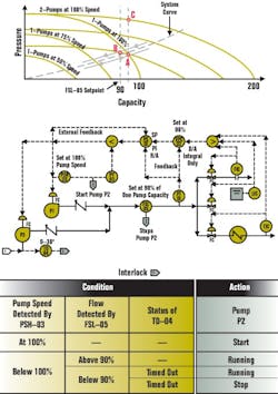
When multiple pumps operate in parallel, their combined head-capacity curve is obtained by adding up their capacities at the same discharge head. The total capacity of multiple constant-speed pumps is found at the intersection of their combined pump curve with the system curve. The same is the case with multiple variable-speed pumps, except that they have a pump surface instead of a pump curve, because velocity is also a variable and it adds a third dimension to their personality.The pump station in Figure 1 can consist of two or more variable-speed pumps. When only one pump is in operation and the pump speed approaches 100 %, the pump speed switch (PSH-03) is actuated and the second pump is started by interlock #1. When both pumps are in operation and the total flow demand drops to 90% of the capacity of a single pump, the second pump is stopped after a time delay. This 030-in. delay (TD-04) guarantees that the second pump will start only if the drop in flow demand is permanent and therefore the pump is not cycled on and off.Stopping/starting
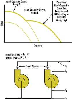
Figure 2 (see below) illustrates that when multiple pumps (A&B) operate in parallel, their combined head-capacity curve is obtained by adding up their capacities at the same discharge head. The total capacity of multiple constant-speed pumps is found at the intersection of their combined pump curve with the system curve. The same is the case with multiple variable-speed pumps, except that they have a pump surface instead of a pump curve, because velocity is also a variable and it adds a third dimension to their personality.The top portion of Figure 1 shows the system curve and pump curves. As the capacity demand rises, the speed of the operating pump increases until (at point A) it reaches 100% and PSH-03 starts the second pump. However, if, at the time of starting the second pump, the speed-control signal was unchanged, an upset would occur, because the speed of both pumps, and therefore their discharge pressure, would instantaneously jump from point A to point C. To eliminate this temporary surge in pressure, PY-03 is provided, which drops its own output signal to x which value corresponds to the required speed, when two-pumps operate at point A.Therefore, when interlock #1 is actuated, the low signal selector selects signal x for control and thereby provides a smooth transition. After the switching, the output signal of PY-03 slowly rises up to full scale and consequently, as soon as it exceeds the output of PIC-01, the low signal selector returns the control back to PIC-01. Once both pumps are operating smoothly, the next control task is to stop the second pump when the load drops below the capacity of a single pump. This switching is controlled by the low flow switch FSL-05, which is set at 90 % of the capacity of one pump (point B on the systems curve).Using the coordinates of flow, pressure and speed, pump characteristics can be described by a three-dimensional surface and the process system the pump serves can be described by another surface. When multiple variable-speed pumps operate in parallel, their characteristic surfaces are summed in the direction of the flow coordinate to obtain their combined characteristic surface.The operating line of a multiple-pump pumping station which is serving a particular process can be found where the two characteristic surfaces meet. A power consumption surface corresponds to the operating surface of the pump or pump station. When the pumping station consists of a large number of pumps (both constant and variable speed), the goal is to meet any load with a combination of pumps that will consume the least amount of power.FIGURE 2: COMBINED HEAD-CAPACITY
When variable speed pumps operate in parallel, their characteristic surfaces are summed in the direction of the flow coordinate.
Smart Pumps and Pump Models
To find the right combination of pumps, start by first determining the prevailing power consumption being consumed at the particular operating load. If smart pumps are used, the power consumption can also be indirectly calculated on the basis of the detected pump velocity and pressure differential. Once the prevailing total flow and corresponding total power consumption are known, check the predictive model to see if there might be another pump combination that will meet the total flow requirement at a lower power consumption. By the use of this model predictive approach, the pump combination that consumes the least amount of power can be identified and implemented (see Figure). Therefore, a model predictive controller (MPC) can be programmed to find the optimum pump selection by summing the required power consumption for any pump combinations at any load. An added advantage of modeling characteristic pump surfaces is the ability to also check for NPSH availability. While much of this data can be condensed in look-up tables, this is not really necessary because the MPC can do the optimizing in real time and can adapt and modify its own model as equipment or process conditions change.Combined with surge-free pump starts and stops and inherent predictive maintenance capability, MPCs can also improve overall plant operation. In addition, they can reduce or eliminate the need for storage, and can improve safety if the particular storage volumes are hazardous in confined spaces. Each model-based application can contribute to a program shell that can be reused, so that the development cost is amortized across many applications. This approach should eventually lead to a user-configurable, all-purpose pumping station optimizer.ISAs Role
Returning to the topic of outsourcing and the potential for regaining our competitive edge through technical innovation, you might say that the number of jobs created by designing optimized pumping stations is small, compared to the job losses caused by outsourcing. Yet, if you sit down and calculate the number of pumping stations in operation and the effort their optimization would take in terms of manufacturing the control hardware, writing the software, designing the individual applications and installations, you might be surprised.You should also remember that pump optimization is one of hundreds of other unit operations that hold optimization opportunities. Pump optimization is only one subchapter in my handbook which contains 175 similar sections.ISA should take the leading role in not only developing the first general-purpose unit operation controllers, but in educating the general public about the potential of process control and automation in maintaining our competitive edge. This role of a professional society is very important, because neither the users nor the vendors can fulfill this role.The users can only be expected to plug into the unit operations controllers the characteristics of their equipment and their process. They can not be expected to develop mathematical models, understand the tuning of velocity and positional algorithms or the peculiarities of external resets, interactions and relative gains. That is not their job. Their job, in the case of a pumping station, is to plug in the system curve and the characteristics of each of their pumps and to push the start button.The same holds true for the PC, PLC, DCS and other vendors of our digital Tower of Babel. Their job is not to learn all the peculiarities of our processes and of the equipment we use. Their job is to provide fast, safe and accurate hardware with good visual displays, that are flexible enough to accept our digital and analog I/O and our software programs for logic, optimization, self diagnostics, auto-start/stop and all other functions that will fulfill the needs of our unit processes.The task that remains for the professional societies, such as ISA, is to develop the universal software package for each unit operation in our industries. It is high time that we stopped controlling flows, pressures and temperatures. It is time to start controlling and optimizing pumping stations, boilers and chemical reactors. Béla Lipták, PE, process control consultant, is also editor of the "Instrument Engineers' Handbook" and is seeking new co-authors for the forthcoming new edition of that multi-volume work. He can be reached at [email protected].

Leaders relevant to this article:
