article_564_tnail

Are you grounded in reality?

Dec. 23, 2005
Control Talk columnists McMillan and Weiner get an insightful reply as to why a plant instrument engineer said the control schemes and instruments successfully used at other locations won't work in his plant.
By Greg McMillan and Stan Weiner, PEStan: We had a reply to the September puzzler, “You Can’t Drop a Control Valve on Him,” from Ralph Quigley that shows considerable practical experience and insight as to why the plant instrument engineer said the control schemes and instruments successfully used at other locations would not work in his plant. Ralph: The plant instrument engineer's answer is correct. The control schemes will probably not work in his plant. The controls from the successful plants have proven that your control logic is valid, so there are two reasons that would keep the "next unit" from operating as well: 
  1. There is something at the new site that makes your team's logic invalid, or 
  2. The plant instrument engineer will not let it be successful. 
To solve this dilemma, the plant engineers must first explain their reasoning behind the statement of expected failure. This explanation may be to you, your team, or management. During the explanation, you need to determine which of the two reasons above are governing. If the engineer has a valid point, then they should become part of the team to solve the new issue.If reason #2 is found to be controlling, then the job gets tougher. There are a number of methods to working through this issue, but first I like to see if the engineer really understands the previously successful control logic. If they do not, then careful coaching is required to guide them through the learning curve. If they understand the logic, then you must find another way to dissuade their dissent. My favorite tactic is to "Make It Their Idea." Let them design the control logic, but work with them, and continually ask leading questions, until the final design looks a lot like your previous version.
Get your spouse their very own copy at www.isa.org/books-- ED.

Greg: We also had an excellent summary from Hunter Vegas on top batch control opportunities, which in response was to the October puzzler, “The Case of the Batch Unicycle.”Hunter: At my company, we do a great deal of batch automation for a wide variety of industries. I would say some of our biggest cycle time reductions have come from: 
  1. Automating the process and moving along material charges and the batch processing without operator intervention. As a result, the batch doesn't have to wait around for operator breaks, lunches, coffee brewing, arguments over weekend football games, etc., etc.
  2. Starting batch heat up after a portion of a material charge is completed. If you need to raise a batch temperature prior to further processing or additional material charge, you can often get a 'jump' on the heatup by starting heating once you have charged enough material to create a decent thermal mass. 
  3. Reduced rework through automation. Despite what you may think every operator runs a batch differently. Batch automation greatly reduces this variability, and lets you iron out and streamline your process. Most often the best cycle time and quality improvements were obtained within a few months after the process was automated.
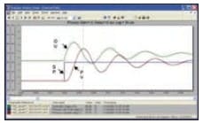
The batch automation package usually provides process trending data that was never available before. Based on that information and a recipe software package that is easy to adjust, the process engineers can fine tune the process to achieve greatly improved production and product quality. Because this time period is so crucial, I try to discourage plants from attempting multiple automation projects, one right after another. This method of project management overwhelms the engineering staff, and nobody ever gets a chance to tweak the process until much, much later, when the round of automation is finally complete. Spacing the projects out a few months allows the staff to regroup between projects, learn from their mistakes, so future projects will run more efficiently. Most importantly, this time allows Production Engineering the time they need to get the most out of their new control system.Greg: If the process permits going from sequential feeds (traditional batch) to simultaneous feeds (fed batch), there can be a huge time savings, particularly if an override or model predictive control system is used to continuously maximize the feeds. Ratio control, Lambda tuning, and mass flowmeters can be used to keep the total masses charged to the batch in the right ratio. The key here is to let the control system do its job and not weave a complex web of discrete process actions. The proper implementation of a feedback control system is more effective, reliable, and easier to maintain than a heuristic set of preprogrammed process actions.Unfortunately, most process engineers think in terms of setting a feed rate based on batch time or the proximity of a process variable, such as temperature, to an operating limit. They come this way out of college. All of the textbooks on control and the entire curriculum are centered on steady state operation, which doesn’t exist in a batch. I know, because I tried to teach process control to senior chemical engineers. Even when discrete process actions are not interfering, controllers in batch processes often exhibit an on-off response because of a too-large controller gain or a too-small reset time. The bizarre tuning settings commonly found in controllers are partly due to the limited time window of a batch phase and the moving target of a batch profile. However, there is plainly a lack of understanding of the basics of feedback control by the process and configuration engineers in charge of the control definition and the operators who set the tuning requirements. Stan: We conclude with a real life story from Hunter Vegas, who we herby elect as an honorary columnist, because of his significant contributions to Control Talk over the years.Hunter: I was working as an instrument engineer at a chemical plant outside of New Orleans. One of the better techs called me to help troubleshoot a problem that bedeviled him. He had a two wire DP transmitter wired to our Texas Instruments (TI) D3 DCS, which I believe was originally EMC, then Rexnord, then TI, then GSE, etc. Anyway, the plant was complaining that the transmitter was reading the correct value out in the field, but the DCS reading was about 20% higher. The tech placed his test meter downstream of the transmitter (in series), and read exactly the same as the transmitter. This suggested there was something wrong with the DCS. However when the tech replaced the transmitter with a two-wire simulator, the DCS readings exactly mirrored the simulator readings. Not knowing what else to do, the tech took the transmitter into the shop for a bench test. On the bench, the transmitter worked flawlessly. However, when the transmitter was re-installed, it still read 20% below the DCS.At this point the tech gave up and called me. After explaining the situation to me, I asked him to do one thing: "Hook your test meter upstream of the transmitter." The tech thought I was crazy, and said the reading would be the same. I told him to humor me and try it. He called back in disbelief. "Now the meter reading matches the DCS reading, but both are 20% above the transmitter reading!" What happened?I knew something our tech did not; the D3 system measures the 4-20 mA signal going out to the field. The return leg is simply grounded and is not measured. In this particular case, the transmitter had developed a weak internal ground. When it was installed in the field, the transmitter was returning the correct 4-20 signal, but a few milliamps were shorting through the meter to ground on the incoming side. The DCS was measuring the combination of the actual transmitter reading and the ground current, and thus read about 20% high. When you placed a test meter downstream of the transmitter, you read the correct signal leaving the transmitter. When you placed the test meter upstream of the transmitter, you saw the leakage current.So why did the transmitter perform flawlessly on the bench? The transmitter was placed on a nice soft rubber non-conducting mat to keep it from getting damaged. Without a path to ground, the transmitter worked flawlessly! Greg: In the following trend (below), the process lag was increased from the 5 seconds for the November trend to 50 seconds, and the controller reset time was decreased from 20 to the 5 seconds needed to eliminate the falter in the response of November trend. What is now wrong with tuning?NEW TUNING TREND
The process lage trend in the November Puzzler was increased from 5 seconds to 50 seconds, and the controller reset time was decreased from 20 seconds to 5 seconds.

This Month's Puzzler:
Valve needs all the trimmings?

Why did Stan include four sets of different-sized trim when ordering a control valve with a Cv less than 0.1?
Send an e-mail with your answer to The Puzzler, CONTROL questions, or comments to [email protected].

  About the Authors
Greg McMillanandStan Weiner, PEbring their wits and more than 66 years of process control experience to bear on your questions, comments, and problems. They’re accompanied in this edition by honorary columnist Hunter Vegas.