
Béla Lipták, Greg McMillan, Greg Shinskey and Harold Wade bring two centuries of process control experience to the knotty question of tuning cascade loops. They had too much good information to fit in just two pages, so we gave them more space. To participate in Ask the Experts, email [email protected].
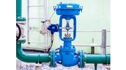
Q: I am working on the temperature control of a batch reactor. In this cascade control system, we have a cold and a hot supply control valve, both of which are manipulated by one master PID temperature controller.
The control system used is DeltaV. Initially, I was using a control configuration where the PD portion of the PID function block was acting on the temperature error, but it did not work well when the loads were high. It worked fine only for smaller heating or cooling cycles.
I was using the following tuning values: Proportional gain: 70; Derivative time: 300.
I tried playing with the above values, but that did not help.
Why do the two valves not open and close at the same rate? Why does the heating valve close too soon as compared to the cooling valve?
Also, is there a way that I can remove the offset, if I let the "PD action act on the error" and not use integral action at all? I guess this can be done with the bias term. How do I calculate the appropriate bias term to remove the offset?
Pallavi Luktuke
[email protected]
A: From your description, it appears that you do not have a cascade loop to start with. In addition, the gain of the controller could not have been 70, but probably 0.7 (70% proportional band), and the unit of your derivative setting of 300 is probably in seconds. A gain of 70 on a chemical reactor is next to impossible, but a derivative setting, which makes the controller project into the future by 5 minutes, is reasonable.
You should remember that the proportional (P) correction is a response to the present value of the error; integral (I) corrects for the accumulated error of the past; and the derivative (D) mode anticipates and attempts to eliminate future errors. Therefore, the cascade master must have all three modes (PID). The job of the cascade slave controller is to serve the master, in this case to keep the jacket outlet temperature at the value dictated by the master.
If your process is self-regulating in the steady state, you can tune it to overcome upsets caused by load changes by obtaining a "process reaction curve" (a curve which shows the reactor temperature response to a step change in the jacket temperature). This is done by first placing the master in manual and changing the setpoint of the slave controller. The response curve to such a step change in heat transfer will be unchanged for a while (dead time) and after the dead time, it will start changing at an increasing rate until it reaches a maximum rate at the inflection point of the curve (reaction rate). Find the PID settings by following Chapter 2.35 in my Instrument Engineer's Handbook.
You did not describe the type of reactor you have. Most continuous reactors are self-regulating (stable), while some exothermic batch reactors can be unstable in the steady state. If your reactor is a continuous exothermic one, you are dealing with a variable-gain process, because the process gain (Gp) drops as the load increases, due to the drop in the heat-transfer efficiency, as a larger amount of heat has to be transferred across the constant heat-transfer area of the reactor jacket. This non-linearity is easy to compensate for. Simply tune the cascade master controller for a gain (Gc) that equals a constant time (0.5 x Gp x Gv), where Gp is the process gain, and Gv is the control valve gain. If the goal of damping is quarter-amplitude damping, use 0.5 as the constant. If you use an equal-percentage control valve (gain rises with load), and if the load rises and therefore the process gain (Gp) drops, then the gain of the control valve (Gv) rises, and, therefore, the gain product (Gp)(Gv) remains relatively constant. Hence, the reactor control will be stable.
If your reactor is an exothermic batch reactor, it can be unstable in the steady state because a second non-linearity is superimposed on the variable gain (which was compensated by the = % valve). This second nonlinearity is a function of time, because at the beginning of the batch, the process gain is low, but with time, as more and more reactants start combining into products, it rises and than drops again as the concentration of the reactants drops and product concentration rises. Therefore, the time function of Gp resembles a bell curve, and this non-linearity requires more sophisticated compensation (c) to maintain stability [Gc = (0.5GpGv)c].
If your reactor is unstable and dead time is dominant (dead time exceeds the lag time of the reactor)—because there are times when, in response to a temperature change, its rate of heat generation can change faster than the rate at which the heat transfer system can change the rate of heat removal—it is uncontrollable. Therefore, such a badly designed (uncontrollable process) has to be redesigned. Some of the redesign options include the reduction in production or increasing the rate of coolant heat transfer by, for example, replacing the liquid coolant with a boiling liquid.
When configuring the cascade loop, keep in mind that it consists of three control loops inside each other. The outer, (or master) loop controls the reactor temperature by generating a temperature setpoint for the inner (or slave) loop that controls the temperature of the heat-transfer fluid leaving the reactor jacket. The slave loop does this by sending a setpoint to the control valve positioner, which moves the valve plug to the desired position.
In order to eliminate cycling, make sure that each inner loop is acting faster than its outer loop. The positioner should be about 10 times faster than the slave temperature controller, and the slave should be 10 times faster than the cascade master. To increase the speed of response, in critical cases, I also use derivative in both the master and the slave controller.
You should also consider protection against reset wind-up that can occur if the cascade master is switched to manual. We protect against this by using external reset (Figure 1). Lastly, carefully follow the configuration shown in Figure 1, except the 50%-50% range split for the valves. If your heating is more effective than your cooling (because of higher ΔT), increase the cooling effectiveness by shifting the split point with a slight overlap towards cooling.
Béla Lipták
[email protected]
A: This is not a cascade system. In a cascade system, the master temperature controller would set the setpoint of a coolant exit temperature controller that manipulates the valves, configured as recommended in Figure 1. The master controller must have the integral mode if offset is to be eliminated, as the heat load changes with temperature and with time in a batch reactor.

Figure 1. If the control valves are provided with positioners, there will be three controllers in series in a cascade loop. All cascade masters should be provided with an external reset from the measurement of the slave controller.
If your controller gain setting is, in fact, 70, this is incredibly high, making the calculation of a bias implausible unless the controller temperature measurement span is incredibly large (e.g. 0 ºF to 1,000 ºF). If the measurement or controller scale range is not that large, the controller output will be bouncing between its output limits. Remember, the controller works with signals in percent.
If the reaction is exothermic, the process could even be unstable in its steady state because it is not self-regulating.
I do not recommend lambda tuning for any process. Both primary and secondary controllers should be tuned as tightly as possible in response to load changes. Derivative is required in both controllers and on the controlled variable only. See my paper, "Exothermic Reactors: the Stable, the Unstable, the Uncontrollable," Chemical Engineering, March '04, pp. 54-59, and in Process Control and Optimization, Ch. 8.10.
Greg Shinskey
[email protected]
A: This application should have a cascade loop, so the secondary controller adjusts the split-range valves. I think you have an exothermic reactor. Exothermic reactants can be unstable at the normal operating point (Figure 2.)

Figure 2. Insufficient heat-transfer surface makes a reactor unstable.
I don't believe lambda tuning is the way to go, because (1) it presumes that the process has self-regulating characteristics, which an exothermic reactor does not, and (2) it only applies the proportional and integral modes. To overcome the open-loop instability of the process, the derivative in the master controller should be on the measurement, but in the secondary controller, it should be on the error. Both should have integral that would eliminate disturbances in the supply temperatures.
Most people split the valve ranges at 50% of the controller output, but your heating valve opens faster than the cooling valve because the strength of the heating effect is greater than the cooling effect. A better configuration can be to shift the split point in the direction of the weaker effect—in this case, cooling—assigning say, 65% to heating and 35% to cooling.
Harold Wade
[email protected]
A: If your controller gain setting is in fact 70, this gain is incredibly high, making the calculation of a bias implausible, unless the measurement span is 1,000º or more. If that is not the case, with this gain setting, the controller output will be bouncing between its limits.
For PD control, the bias parameter of the PID block should be set to eliminate the offset, so if the controller output is 70% when the temperature has settled, and the error is 3º above set point on a 50º to 100º scale, with a controller gain setting of 2 of a reverse acting controller, then the estimated bias is:
Bias = settled output + offset percent error (process variable % – setpoint %) x controller gain x controller action sign (-1 for reverse) = 70% + (6%) x (2) x (-1) = 58%.
The estimated bias adjustment must be tested with close observation. Whenever the PID is switched from manual to automatic, the bias is automatically corrected by an invisible amount by DeltaV to provide a bumpless transfer.
It is unlikely that you have a linear constant process gain. Valves generally have a nonlinear installed characteristic; the process is nonlinear; and heating and cooling have different process dynamics (e.g., speeds of effect). For these and other reasons, PID rather than PD control is preferred unless the reactor is exothermic and has a runaway response (accelerating response) when the controller is in manual.
If PID is used, the integral time should be large for slow integrating processes, which yours probably is. You could start an integral setting of 10 times your derivative time if you are not presently experiencing oscillations. If the present response falters or oscillates, your rate setting is high.
If the approach to setpoint is smooth, but oscillates after you reach it, your gain setting is high. If, with these settings, the overshoot is not excessive, you can decrease the integral time. Low gain settings on integrating processes cause slow rolling oscillations and overshoot, while too high a gain causes instability. Therefore (P)(I) should exceed 4/(process gain).
Since the valves are nonlinear and the process dynamics for heating and cooling are different, you should use different tuning settings based on which control valve is being throttled. The adaptive control feature in DeltaV Insight can be used to identify (Version 9.x) and schedule tuning settings (Version 10.x) as a function of controller output.
If the heating effect of your installation is twice as large as the cooling effect, set the split range point so that the portion of the controller output for throttling the heating valve is twice as large as the portion for throttling the cooling valve.
You should contact your DeltaV representative to help you use the DeltaV PID block options and advanced capability such as DeltaV Insight.
Greg McMillan
[email protected]


Leaders relevant to this article: