Q: I would like to learn when we have to use two blowdown rings and when only a single blowdown ring in safety relief valves and which is superior?
M. Ulaganathan
[email protected]
A: Let me first explain the role of blowdown in regular pressure relief valves (PRV). When the PRV is closed, the system is a static one with no kinetic effects. Therefore, the pressure at the point of spring balance is equal to that in the protected tank. When the PRV is open, its inlet pressure is less than the pressure in the protected vessel because of the inlet pressure drop. This discrepancy between relieving and static conditions requires the allowance for blowdown, which is the amount of pressure by which the protected tank's pressure has to drop below the PRV's set pressure for the valve to reseat. The normal blowdown of a PRV is between 2% and 7% of set pressure. Pilot-operated PRVs can reduce the blowdown to about 2%. Industrial practice is about 7%, which means that the normal operating pressure must be under 93% of set pressure, and fired boilers require that the PRVs reach their full lift at a pressure not greater than 3% over their setpoint and reclose within the maximum blowdown values given in Table 1.
Table 1: ASME's Blowdown Recommendations for Fired Boilers and Associated Tanks Operating at up to 375 PSIG.
The position of the adjustable ring on the PRV nozzle controls the blowdown by establishing a secondary orifice area as the valve opens and closes. Blowdown is set by first bringing this ring all the way up to the disc (this corresponds to the maximum blowdown position) and then lowering it. If blowdown is an important consideration, field tests usually must be made after the PRV is installed. Pilot-operated valves can usually be set for smaller blowdowns. Three percent is fairly standard for a POPRV, and as little as 1% can be achieved in some cases.
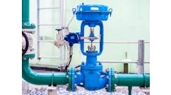
In order to make fine adjustments, double blowdown rings are used (Figure 1). The upper blowdown ring is usually factory-set. The lower blowdown ring is also factory-set to achieve the appropriate code performance requirements, but it can be altered. In its top position, the valve will pop rapidly, minimizing the overpressure value, but correspondingly requiring a greater blowdown before the valve re-seats. When the lower blowdown ring is adjusted to its lower position, there is minimal restriction in the huddling chamber, and a greater overpressure will be required before the valve is fully open, but the blowdown value will be reduced.
Béla Lipták
[email protected]
A: I can do no better than to refer you to a comprehensive discussion of safety valves:
Introduction to Safety Valves
Richard H. Caro, CEO, CMC Associates
[email protected]

Figure 1. The double blowdown rings on an ASME-type safety valve. (Courtesy of Spirax-Sarco Limited)
A: The blowdown ring on a relief valve is adjusted to set the reseat pressure of the valve. (The spring determines the pressure at which the PSV will lift, and the blowdown ring determines when it will reseat.) A two-blowdown ring design provides the ability to adjust this reset pressure very accurately, which is required for most ASME Section 1 application (boilers). Therefore, you will typically see the two-ring design for boiler relief valves. However, most applications don't require so fine a blowdown setting, so they use the single-ring design.
Short answer, the two-ring design is better and allows tighter control of the blowdown setting, but unless you are dealing with a boiler, ASME Section 1-type valve, you usually don't need that kind of very fine adjustment.
Hunter Vegas
[email protected]
Q: We have a pipe which runs 30 cm above ground with an orifice plate in it, and we want to install the dp transmitter in it, which normally should be below the pipe, the elevation of which we can not change. Can we install the transmitter above the pipe taps?
Secondly, we do not have the ISO 5167 straight-run requirements up and downstream. Is there any flowmeter which will work without that?
Lastly, Rosemount has an new model orifice plate (Figure 2) that needs only four pipe diameters upstream and downstream, but I can't find information about its pressure drop? Is there a way I calculate its pressure drop?
Hassan Mommadzadeh
[email protected]

Figure 2. This Rosemount 3051SFC orifice flowmeter needs only four pipe diameters upstream and downstream.
A: A horizontal takeoff from one side will work adequately—a slight slope (1:10) up to the tapping points will ensure any air bubbles can be displaced.
The Rosemount conditioning plates do work, and I have had several installations immediately downstream from pump/checkvalve assemblies (6D, 2D), which checked well against a turbine meter—minimum-flow installation within a piping layout that forgot the meter runs!
Permanent loss is close to that of a single orifice with the same nominal beta and dp. The sizing equation gives this.
Ian H. Gibson
[email protected]
A: Use the Darcy Equation (an approximation only, because velocity immediately at the outlet of the orifice is unknown). Normal calculation of outlet velocity is based on mature velocity profile, such as at 10D downstream of orifice:
[(2.gc.144.ΔP) / ρ] = 1.5 v2
Where:
v is the inlet velocity in feet/second
P is pressure in psi
ΔP is pressure drop in psi
P is density in lbm/ft3
gc is universal gravitational constant, 32.2 (lbm ft)/(lbf.s2)
1.5 is the loss coefficient of the orifice plate with four holes (Figure 2).
(Reference to Crane Technical Publication 410: Inlet loss coefficient of sudden contraction is 0.5; outlet loss coefficient of sudden expansion is 1).
These four holes are in parallel; therefore, their effective loss coefficient equals that of one orifice of equivalent hydraulic radius. The line loss coefficient is usually negligible compared to the loss coefficient of the orifice. The orifice plate with four holes was not in any approved standard. I hope to see experiments showing 4D is all that is required for establishing mature velocity profile for the orifice plate with four holes.
Gerald Liu, P. Eng.
[email protected]
A: To connect the DP transmitter to the orifice plate for all liquids, the connection must be under the midpoint of the pipe to avoid air/gas entrapment in the sensing line (Figure 2).
The orifice arrangement by Emerson/Rosemount has a flow conditioner in the orifice plate holder, the accuracy of which will be dependent on the stability of the flow and the process variables. The conditioner compensates for upstream and downstream lengths. The conditioning element will make the system more expensive, but with your constraints, it might be worth it.
Alejandro Varga
[email protected]

Figure 3: On right: preferred, on left: alternate connection.
A: If you use a DP with remote diaphragm seals/capillaries and flanged tappings on the orifice flanges you can mount above the orifice. You would have the tappings coming off the sides. Another option is a Coriolis Mass flow meter.
Simon Lucchini
[email protected]
A: I have not personally had pipe tap below the pipe, but we once had a major issue with the lack of free pipe downstream. We had 4-5 D straight pipe downstream and then a 90-degree bend. he dP cell told us we had reverse flow of water, which could not happen in a 500-PSI pressurized system. The eddy currents at the elbow really messed up the flow measurements.
Bruce Land
[email protected]