Andrew Fry, Ph.D., is director of the Industrial Combustion and Gasification Research Facility at the University of Utah.
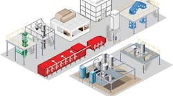
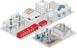
The original facility housed a 1.5-MW, pulverized coal research reactor to investigate the formation and control of oxides of nitrogen in utility boilers. Since then, ICGRF grew to 30,000 sq ft in three buildings with eight pilot-scale reactors and many pieces of small research and support equipment (Figure 1). The capacity of its combustion and gasification test facilities range up to 1.5 MW (5.1 MM BTU/hr). The original facilities were monitored and controlled by Opto 22's automation systems, and more were added as ICGRF expanded. Its current project consists of removing all legacy control hardware and updating it with Opto 22's Snap PAC hardware and software to form a modern, integrated automation system.
Figure 1: The ICGRF at the University of Utah performs research on coal, shale oil, biofuel, municipal waste and other fuels for the U.S. Department of Energy, U.S. utilities, Praxair and other companies, and is controlled by Opto 22's automation systems.
Credit: ICGRF
Research performed at the ICGRF includes:
- Underground thermal treatment of coal and oil shale to produce gaseous and liquid fuels;
- Investigating CO2 capture combustion technologies, including oxygen combustion, gasification and chemical looping combustion;
- Fuel switching and combustion of multiple fuel blends including coal, petroleum coke, fuel oils, natural gas, biomass (hog wood, algae, switch grass, bagasse, pelletized biomass, corn stover, etc.), municipal waste, biohazardous waste and many other fuels.
See Also: Oil and Gas Leads Demand for Automation Pros
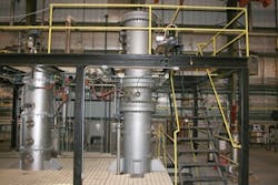
Process equipment to perform this research includes entrained and fluidized bed gasifiers, grate-fired and oxy-fuel combustors, a circulating fluidized bed reactor, chemical looping systems, diesel engines, fire test facilities and process heaters. This equipment provides comprehensive capabilities for gas- and liquid-phase analysis and particle characterization. For example, the pressurized fluidized-bed gasifier processes solid fuels, such as biomass and unreactive fuels requiring a long solids-residence time. The gasifier is capable of gasifying up to 32 kg/hr of fuel with steam or air, with or without adding oxygen (Figure 2).
Figure 2: ICGRF's pressurized, fluidized bed gasifier processes solid fuels such as biowaste to investigate fuel reactivity, tar production and quality of synthesis gas.
Credit: ICGRF
Research Returns Results
Research performed at ICGRF is funded by industrial and government entities, and the goal of each project depends on the funding institution. During 2008-13, ICGRF had a research grant from the U.S. Department of Energy (DoE) for a program entitled "Characterization of Oxycombustion Impacts in Existing Coal-Fired Boilers," and more than 12 organizations from the U.S. and other counties participated. Its purpose was to establish feasibility and identify potential roadblocks for retrofitting the most common coal utility boiler in the U.S. so it could reduce or eliminate emissions with CO2 capture and storage, and reduce greenhouse gas emissions and mitigate climate change.
This program was a precursor to the FutureGen 2.0 project, which is a full-scale demonstration funded by the DoE. Results from this program were used in decision making for the FutureGen program, and experimental work was conducted on the oxy-fuel combustor and 1.5-MW multi-fuel furnace.
There have been several other DoE-funded programs of this size in the lab’s history. Subjects studied ranged from reducing emissions from coal-fired utility boilers to producing data sets detailing heat transfer in jet fuel pool fires.
Growth Requires Upgrades
As the ICGRF grew, it needed improved control systems. Its legacy Opto 22 automation did a good job controlling individual systems, but a plant-wide automation system was needed, so operators and research engineers could control, monitor and coordinate all equipment and processes from a central location. The upgrade path ICGRF took is similar to the one followed by many commercial facilities where islands of automation are joined together, making the upgrade project particularly relevant to students and research partners.
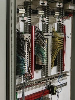
One might assume that upgrading seven separate automation systems and 1,360 total I/O points would be a major undertaking. Some equipment was controlled by legacy Opto 22 Mistic G4 control systems, and many of the newer furnaces had more recent Opto 22 hardware and software. However, we at ICGRF olfound that replacing the older hardware with modern Snap I/O and Snap PAC System controls was largely straightforward and uncomplicated (Figure 3).
Figure 3: Updating the I/O and controls with Opto 22 Snap PAC hardware was a simple replacement process.
Credit: ICGRF
One reason why replacing the older Opto 22 hardware was relatively simple is that both modern and legacy Opto 22 equipment share the same programming and configuration procedures. This made it easier to set up new control programming and I/O on older systems. This common foundation between new and old systems allowed students to install and configure the hardware without having to learn different standards, networks and procedures.
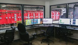
In addition, Opto 22 hardware supports Ethernet communications, which made it easy to connect peripheral equipment such as analyzers, chromatographs, remote I/O and similar devices. Ethernet also made it feasible to network all the remote systems into a central control room (Figure 4).
System Upgrade Steps
Figure 4: The upgrade and network improvement enable all process operations at ICGRF to be monitored and controlled from this central control room.
Credit: ICGRF
The first step in the upgrade was to review the old control programs and account for all the I/O points involved. This included three control programs for the 1.5-MW multi-fuel furnace (L1500), circulating fluidized bed combustor and grate-fired combustor (stoker), plus building services and analyzers for 422 individual I/O points.
A list of I/O points was created for ordering new hardware. One goal of the upgrade was to be as minimally invasive as possible to the existing wiring. Fortunately, the engineer who originally set up the automation systems did a good job wiring I/O points to terminal blocks instead of directly to the control modules, which facilitated reuse of existing wiring.
However, there was no documentation describing the mapping of the wiring, so one of the undergraduate students mapped and labeled all wiring. Then the undergraduates removed all the old control hardware.
The next step was to install and wire the new control hardware for the building services and the L1500 multi-fuel furnace, a task assigned to the post-doctoral researcher and the PhD student. Due to the earlier preparation, this went fairly quickly and smoothly.
The next step was to troubleshoot each of the control points. This took a bit longer. Some of the 4-20 mA analog points had to be rewired because they were not all uniform in their power and grounding requirements. This turned out to be a valuable troubleshooting exercise for the students.
Next, the PhD student recreated the old control strategy in the new software. Some of this was performed by importing parts of the existing strategy into the new software, but much of the original strategy had to be recreated. Once this step was completed, an undergraduate student duplicated the process for the stoker furnace. With minimal direction, the student was able to install and wire the new hardware, troubleshoot it and create the control strategy. This same student is currently working on the display strategy for both furnaces.
I provided guidance during the upgrade, and there were many meetings focused on wiring diagrams and I/O point manufacturer spec sheets, but I have yet to touch a tool on the retrofit project because the students were able to perform the required work themselves. I did install one of Opto 22’s groov Box hardware appliances, which I found to be straightforward too. It gives us the capability to securely monitor and control our equipment from off-site using a PC, tablet or smartphone (Figure 5). This remote access is an important capability because we have to leave furnaces running in our facility with no supervision during the heat-up and cool-down phases of a project
Central Control Room
Figure 5: Operators and engineers can use Opto 22's groov appliance to monitor processes from a PC, tablet or smartphone.
Credit: Opto 22
ICGRF is always looking to control costs, and Opto 22 assisted greatly in this by supporting the university with much of the automation system hardware. Because their automation systems use open architectures, we’re able to use off-the-shelf PCs and Ethernet networking hardware, which greatly reduces expenses. Students generally have a great deal of familiarity with PCs and with Ethernet, making the learning process for these critical automation system components relatively straightforward.
Beyond having a local operator interface in the central control room, remote monitoring and control is critical. This is provided by Opto 22’s groov mobile interface, which allows secure browser- or app-based access from virtually any device connected to the Internet, including remote PCs, tablets and smart phones. Remote access and an operator interface are simultaneously provided to any number of devices on a royalty-free basis.
More Benefits Gained
Finally, what could have been an overwhelmingly complex project to upgrade seven automation systems with 1,360 I/O points and integrate them into a plant-wide system turned out to be a fairly straightforward exercise accomplished by student engineers, thanks to Opto 22's open architecture, common software and the remote access capability of its automation components.
Each year, about 70 chemical engineering students conduct experiments or examine a process controlled by Opto 22 automation systems as part of a senior design capstone course. This exposure provides students with a unique opportunity for hands-on experience with industrial-grade automation and data acquisition systems before entering the workforce.
"We find these activities greatly enhance the presentation of a wide variety of chemical engineering principles, including separation, heat transfer and process control," adds Milind Deo, professor and chairman of chemical engineering at the University of Utah. "Most students cite this class as the most important part of their curriculum. It’s clear these educational experiences make a long-lasting impact on our students and serve them throughout their careers."

Leaders relevant to this article:
