
Read Part 2: Why and how to make power and shielding connections.
Grounding can be the ultimate common cause due to its ubiquitous nature of connecting everything electrical together, and a great unknown because much of it and its operation are invisible to us. This article discusses what makes up a good instrument grounding system and why. It doesn’t cover all the details about instrument grounding systems (which would take a book or two), but rather some of the basic principles that lead to good practices, as well as their technical basis.
First, we must divide the instrument systems into the incoming power side, which is nominally the AC side, and the instrument side, which is nominally the DC side (Figure 1). The DC side can be further divided into the DC power side (nominally 24 VDC), control and signal. The AC and DC power sides are normally isolated through transformers, while on the DC side, the power and signal are shared. Our discussion will be primarily about the DC side, but for reasons described later, the grounding system is typically shared by both sides.
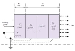
Figure 1: Instrument systems can be divided into the AC side and the instrument side, which is nominally the DC side. The DC side can be further divided into the DC power side (nominally 24 VDC), control and signal. The AC and DC power sides are normally isolated through transformers, while on the DC side, the power and signal are shared. The grounding system is typically shared.
Why we ground
The main reasons we ground our systems are:
- Personnel safety,
- Electrical system protection,
- Lightning protection,
- Electrostatic discharge protection,
- Electrical noise control,
- Intrinsically safe circuits,
- Power quality, and
- To provide a reference plane for our electrical and electronic circuits and systems.
Personnel safety: This is primarily a concern on the AC (high-voltage) side of the instrument system. Maintenance personnel test and repair instrument systems, and the operator may also interact with the instrument system’s front end and field instruments. Because of the low voltage (nominally 24 VDC), the instrument side is often worked without concern about electrical shock. An instrument tech may be in for a rude surprise, even a fatal one, when working on an instrument circuit where an ungrounded DC instrument circuit has come into contact with a higher voltage source (e.g. 120 or 277 VAC) that didn’t trip the high-voltage circuit overcurrent protection.
The National Electrical Code (NEC) Article 250 and other application-specific NEC articles provide requirements for grounding for personnel safety. This is a U.S. code, also known as National Fire Protection Association (NFPA) 70, which is used worldwide. However, each country or legal identity may have their own electrical code, or provide additional requirements to the NEC. You can’t take exception to requirements of the NEC or similar codes just because the system is an instrument system, not an “electrical” system. Equipment grounding and bonding are used to help ensure that there's a low impedance path back to the source during the fault conditions. This allows the system overcurrent protection to open up, protect the electrical system and remove dangerous voltage from the circuit in a timely manner.
Common codes and standards for grounding for personnel safety are:
- NFPA 70, National Electric Code (NEC), Article 250 and specific application articles.
- IEC 60364, Electrical Installations for Buildings, Part 5, Section 54
- IEEE 142 Std. – IEEE Recommended Practice for Grounding of Industrial and Commercial Power Systems (commonly called the Green Book)
- IEEE Std. 80 - IEEE, “Guide for Safety in AC Substation Grounding”
Electrical Instruments in Hazardous Locations by Ernest C. Magison has an excellent chapter human electrical safety. Soares' "Book on Grounding and Bonding" is an excellent general reference on grounding and has a chapter on grounding of electronic systems.
Electrical system protection: The NEC also provides requirements for electrical protection to limit the damage to equipment and wiring. This is also safety-related as it minimizes the potential of a fire caused by an electrical source. A properly designed grounding system for the AC side of our instrument system can minimize the potential damage to equipment from an electrical fault, surge, lightning strike, etc., and contribute to the reliable operation of the equipment.
Common codes and grounding standards for this are essentially the same as those for electrical safety given above. NEC Article 250-50 also requires that all grounding electrodes that are present at each building or structure served shall be bonded together to form the grounding electrode system (commonly called a ground grid in petrochemical facilities).
This has given rise to the one of the most controversial aspects of grounding—whether it is wise or necessary to connect the DC side of the instrument system to that noisy, nasty electrical safety ground. In the early days of DCS systems, manufacturers commonly called for an isolated, clean ground. This requirement has for the most part been superseded, but still raises its ugly head occasionally, both as a manufacturer’s requirement and in questions raised on various Internet forums. The answer to the question by NEC is a solid “yes.” Later, we'll talk about why this is actually a good idea, as well as the fact that there is no such thing as a “clean” ground.
Lightning protection: Lightning is always a concern for instrumentation systems, and increasingly so with new technology that has ever-smaller-dimension digital circuitry, smaller signal-to-noise ratios, and tighter common mode specifications. These make our digital instrumentation more sensitive to lightning, RF generation, induced currents and power quality disturbances.
The common standards applied to lightning protection are:
- NFPA 780 – “Standard for the Installation of Lightning Protection Systems”
- API 2003 – “Protection Against Ignitions Arising out of Static, Lightning, and Stray Currents”
Electrostatic discharge protection: This is primarily a concern in handling, touching or being in close proximity to digital electronic chips and cards. Analog electronics are not as sensitive.
Standard manufacturer’s recommended grounding practices for handling digital equipment should be followed. It's also common practice for raised-floor installations to specify a resistivity for the floor tile or a resistance to ground. For example, IBM specifies no greater than 2 x 10¹⁰ ohms to the ground reference. ANSI/ESD S20.20 has a specification of ≤ 1 x 10⁹ ohms. As you can see, a little ground goes a long way when dealing with static electricity, but it's a necessary consideration. This is normally satisfied by specifying the proper floor tile, designing a good floor stringer grounding system, and using grounding wrist straps when needed.
Static electricity can also generate radio frequency interference (RFI) that can interfere with the operation of instrumentation, with lightning being the extreme case. I'm aware of a control room installation where the operator’s chair seat backing crinkled as the operators adjusted themselves in their chairs, which generated small static electricity discharges and generated RFI that interfered with their control displays.
A common refrain is that ground is a place to drain your noise. The ground is not a sump for noise, and can actually be a source of noise. A basic principle of circuit electricity is that electricity always seeks to return to its source. This principle applies to noise: once coupled into a circuit, noise always works in complete circuits, and ground can serve as a return path for noise.
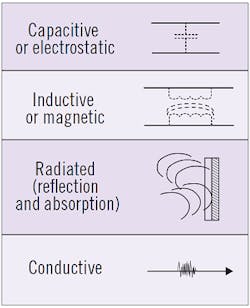
Most noise of interest is coupled into the instrumentation circuits by four methods: capacitive, inductive, radiated or conducted (Table 1). We will talk more about this when we talk about grounding of shielding.
Intrinsically safe circuits: For facilities that use intrinsically safe (IS) circuits to satisfy the requirements for instruments in classified hazardous areas, grounding can be an issue for certain types of intrinsic safe barriers. Zener barriers (Figure 2) require a high-integrity ground to shunt any dangerous electrical energy. The nominal grounding specification is a maximum resistance of 1 ohm. The intrinsic safety ground is connected to the plant safety ground grid. For the intrinsic safety ground, the concept of an equipotential ground plane is important to ensure that the ground potentials in the intrinsically safe circuit are as equal as we can make them to prevent a spark due to a voltage differential between circuit parts and ground. Transformer or galvanically isolated barriers typically do not require a ground connection.
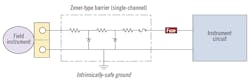
Figure 2: Zener barriers in intrinsically safe (IS) systems require a high-integrity ground with a maximum resistance of one ohm. The concept of an equipotential ground plane is important to prevent a spark due to a voltage differential between circuit parts and ground.
The standards for intrinsic safety are:
- ISA RP 12.06.01, “Recommended Practice for Wiring Methods for Hazardous (Classified) Locations Instrumentation Part 1: Intrinsic Safety”
- ANSI/ISA 60079-11 (12.02.01) – “Explosive Atmosphere – Part 11: Equipment protected by intrinsic “i””
- NEC Article 504 – “Intrinsic Safe Systems”
Power quality: A stable ground reference is important for power quality, particularly with distributed control systems. Good grounding practices are also necessary for surge protection devices to work properly. Following the grounding practices of the NEC and the IEEE std.1100, “Recommended Practice for Powering and Grounding Electronic Equipment,” commonly called the IEEE Emerald Book, will help achieve good power quality and good grounding engineering practice.
Circuit reference plane: Grounding is also used to establish a common, stable voltage reference, so complex and sometimes widely distributed instrument systems can understand each other’s signals. Circuits work much better if they have a common reference between them.
Common ground
Grounding can be a technically difficult subject primarily because of its complexity (breadth of scope, infinite number of potential connections, internal and external actors and bad actors, etc.,) and its uncertainty due to invisibility (can’t see what is going on below the surface, the ground is different anywhere you look, unknown influences, limited available models that can help the practicing engineer, etc.). It also can raise the specter of many electrical engineers’ least favorite subject—electromagnetic fields and Maxwell’s equations—when circuit theory isn’t enough. Fortunately, much of the basics can be understood by analogy and a bit of circuit theory. This can lead us to some good engineering practices in regards to grounding instrumentation systems.
We discuss three topics that commonly arise when engineering instrument grounding. The first is here and the others are in Part 2:
- What should the ground resistance be?
- Do I have to connect my clean instrument ground to that dirty power ground?
- Do I connect my shields to ground at one end or both?
What should the ground resistance be?
A common grounding question is what the ground resistance should be for a DCS/PLC system (this question applies to the DCS/PLC ground prior to any connection to other grounding systems). The National Electric Code Article 250.53 specifies that a second ground rod is required if the resistance of a single ground rod is greater than 25 ohms. The various DCS manufacturers have a recommend resistance range from one to five ohms. Communication sites specifications are typically on the order of five ohms or less.
The question also arises as to whether we should be concerned about impedance rather than resistance. For instrument systems that have high-frequency components in the ground circuit, impedance is generally a concern for the above-ground part of the ground system as conductors tend to change from resistors to inductors as the frequency goes up. It is not as much a concern for the below-ground part of the instrument ground system.
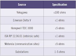
In general, you should make every attempt to meet the manufacturer’s recommended ground resistance specification. If this is not possible, the DCS ground should be equal to or better than the associated power system ground resistance specification. Various grounding resistance specifications are given in Table 2.
Testing of grounds to determine resistance is beyond the scope of this article. Testing the instrumentation ground prior to connection to the main power grounding grid, using traditional means such as the “fall of potential” or three-point method, is generally adequate. Some designs have a switch for testing purposes on the connection line between the instrument ground and the system power ground grid with a spark gap around the switch for safety purposes.
There are some good primers on earth resistance testing by Megger, Fluke and Aemc. It's recommended that the tester use a AC test current source. You should not try to use a clamp-on ground tester for the initial test, but it can be used for subsequent checks after connecting to the main power grid and doing a benchmark test. The clamp-on ground tester is an excellent tool for determining if grounding has degraded by comparing readings to an initial benchmark.
It can't be overstressed that a grounding system must maintained, which means that it has to be periodically inspected and tested. This also applies to the power system ground grid that it’s connected to. If you let your grounding system degrade, you're asking for trouble, and not just from an instrument system perspective, but from an overall electrical perspective, too.
About the author:
Frequent contributor William (Bill) L. Mostia, Jr. PE, Principle Engineer, WLM Engineering Co., can be reached at [email protected].
[sidebar id=1]
