How to optimize pumping cost
This column is moderated by Béla Lipták, automation and safety consultant and editor of the Instrument and Automation Engineers' Handbook (IAEH). If you have an automation-related question for this column, write to [email protected].
The Coriolis meters require minimum pressure to function. Now, the pump can’t meet the minimum pressure for both towers in service, so only one tower is in service. A new pump and VFD will be installed. Two pressure transmitters will also be installed—one right after the pump, the other up by the towers just before the split to the two flowmeters. There is an estimated 30-45-second lag between a change in pump speed and an observed change in pressure at the flowmeters.
The plan is to use a new PID pressure loop to maintain the pressure just downstream of the new pump by adjusting the VFD. The second transmitter up by the flowmeters will be used with logic that helps avoid low pressure at the flowmeters: If pressure up there falls below a threshold, logic will put the flow loops in manual and start closing the valves to build pressure back up.
The question is whether this design concept is sound and valid. Or will there surely be interaction? Or maybe it will work but we have to try it and fine tune it?
William Love
[email protected]
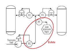
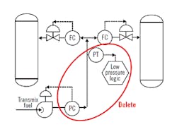
Figure 1: Delete pressure controls because pressure and flow can't be independently controlled. Once flow is controlled, the pressure is determined by the system.
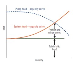
A: This is a valuable question because it applies to all pumping system applications. The important point to remember is that one cannot independently control both the pressure and the flow of liquids flowing in a pipeline, because pressure is dependent on flow. Therefore, the proposed control system (Figure 1) is unworkable.The relationship between flow and pressure is determined by the pump and system curves (Figure 2) and the operating pressure (sum of static head and friction loss) is at the point where the two curves cross.
Liquids are incompressible, so there is no dead time between flow and pressure. Therefore, the cited dead time of 30-45 seconds is in error. Cascade control can’t be used because the flow and pressure time constants are nearly identical, while for good cascade control, the slave must be an order of magnitude faster than the master.
If you want to save pumping energy, you can control the speed of the variable-speed pump using a valve position controller (VPC). The VPC minimizes the valve pressure drops by opening the valve that is most open to 90%, all the time. As shown in Figure 3, if the system was designed so that normal operation would require an average speed of about 50%, you will require only 13% of the horsepower of using a constant speed pump (100% speed in Figure 3) .
Figure 2: The system curve determines the relationship between flow and pressure. The operating pressure will be at the point where the pump (dotted) and the system (solid) curves cross.
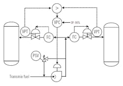
For a variety of other pump optimization schemes, read the pump chapter in the 4th edition of Volume 2 of my handbook.My recommendation for your system is shown in Figure 4. Note that I also added a pressure safety valve (PSV) to protect your system against overpressure.
Millions of dollars could be saved in various industrial applications if all pumping energy costs were minimized the same way as shown in Figure 4..
Béla Lipták
[email protected]
A: I suggest that you review the design of the centrifugal pump. With a given impeller, the pump will pump a volume of liquid at a given head at a given speed. If the pump can’t provide the required head at a given speed, then increasing the rotational speed at the VFD will increase the head. The governing law of physics is the Pump Affinity Law:
- The flow (GPM) varies proportionally with the change in speed. This means that twice the speed is twice the flow. One-third speed is one-third the flow.
- The pump head (pressure) varies with the square of the change in the speed. Doubling the speed generates four times the head. At 80% speed, the head generated is 64%.
- The power requirement (horsepower or kilowatts) varies by the cube of the change in speed. Twice the speed would consume eight times the power; half the speed would require one-eighth the power to drive the pump.
Figure 3: If a valve position controller (VPC) is added, this independent control loop can keep the most open valve always 90% open by modulating the pump speed. If the pump is over-sized, the operating cost savings can be substantial.
A speed change at the pump must immediately appear as a pressure increase at the flowmeter in this liquid-filled system. The 30-45-second delay is just not physically possible; the pumped liquid has to go somewhere. If the VFD responds to the speed change properly, the pressure increase should be instantaneous. Many VFDs have filters installed on speed change to prevent too rapid a speed change that might result in pipe hammer. However, 30-45 seconds seems out of reason.
In a filled piping system, VFD speed change will result in an immediate change in flow rate and pressure head unless a ramping function is configured or the pipe is not filled with liquid. What you describe is not possible with a filled pipe.
Dick Caro
[email protected]
Figure 4: When optimized, the valve position controller (VPC) always minimizes the system pressure drop by keeping the most open valve at 90% open.
A: From the information available, you are up against two very critical conditions: Dead time is very detrimental to the best performance a feedback controller can accomplish, as integrated error is directly proportional to the dead time. You can always use a PI-Deadtime compensated, however, it comes at a price of reduced robustness margins. The stability of the loop will depend on the precision of the estimation of the dead time, and stability will be compromised when the dead time estimation is either too short or too long.
Now, it is very strange that you have such a long dead time in the flow of an incompressible fluid, so you may want to verify the correct operation of your field devices. The interaction of liquids is typically severe and even detuning one of the controllers may not give the stability and the performance your process may require. Decoupling also has a price to pay—the higher the relative gain, the narrower the stability margin of the system with respect to the mismatch between the actual process and its model.
If the pump discharge pressure can exceed the pipe pressure rating, that is unacceptable. From the control viewpoint, you should install high pressure control override to either slow down the pump or open up the flow valve (s). Not pretty, but functional. And I would strongly recommend the installation of a pressure relieve valve.
S. Nino
[email protected]


