This column is moderated by Béla Lipták, automation and safety consultant and editor of the Instrument and Automation Engineers’ Handbook (IAEH). If you have an
automation-related question for this column, write to [email protected].
Q: I'm working at a wastewater treatment plant where we're using 50 weight-percent NaOH to neutralize the water in a mixing tank. To cover the rangeability requirement of the application, we're sequencing two control valves in parallel. I'd like to learn how we can reduce or eliminate the limit cycling that occurs near the point where the reagent requirement is under the minimum flow of the large valve, but under the maximum flow of the small valve.
Harry Crowney
[email protected]
A: Rangeability requirements are usually determined by the titration of a 50 ml or so wastewater sample in a laboratory, and the results are typically plotted as pH vs. milliliters of reagent used. To convert this information into gallons per minute (gpm) of industrial-strength reagent required per 1,000 gpm of wastewater, one has to know the reagent concentration in units of normality (N).
For example, if 10.2 ml of 0.01 N of NaOH reagent was used to neutralize a 50 ml sample of wastewater, the normality of the 50 ml sample was N = (10.2 / 50) 0.01 = 0.00204. If in the plant, a 50% NaOH reagent (N = 19.1) will be used; then, neutralizing 1,000 gallons of wastewater will require 1,000 (0.00204) / 19.1 = 0.107 gallons of this reagent.
We'd usually select a control valve size to deliver twice the required maximum reagent flow. This degree of oversizing is advisable to allow for errors in the estimate, and to provide a margin for dynamic correction during recovery from load changes. A similar calculation should be made for the anticipated minimum load to estimate the required minimum reagent flow. The ratio of the two flows will give the rangeability requirement for the control system.
One option is to deliver the reagent by metering pumps, if a 20:1 rangeability is sufficient. It's usually insufficient, and therefore one metering pump usually isn't an acceptable option. If one control valve is used and it doesn't have enough rangeability (rangeability is 50:1 for equal percentage, 35:1 for linear, 20:1 for quick-opening), either the maximum reagent flow will be insufficient for the largest plant load, or the minimum will be too much at low loads. In either case, the treated effluent will be off-specification, and the penalty for that can be severe.
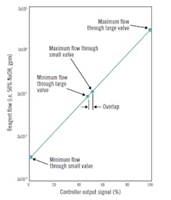
Figure 1: The dots on the lines represent the calibration limits for the valve positioners. The smaller valve is throttling over the controller output range of 0-52%, and the large valve is throttling from 48% to 100%. A logic interlock must be provided to switch one valve off and the other one on when the controller output reaches their respective ranges.
If the minimum controllable flow is too large, limit cycling will result. In case of a single reagent valve, this occurs because, when the valve is shut, the load will drive the pH away from setpoint, so the controller opens the valve, and after that, because the minimum controllable flow is greater than what is needed, the pH will overshoot the setpoint, which will cause the controller to close the valve once more. This cycle will repeat, in a generally saw-tooth pattern. If the amplitude of the cycle is within acceptable pH limits, then the plant can live with it and can just place a vessel (even unmixed) downstream to attenuate the cycle.
Your situation with the two valves in parallel is similar to this case because, in the overlap region, both valves are open to some degree. When the reagent demand rises, the large valve starts opening before the small one has fully opened, and therefore the reagent flow becomes too high, causing the pH oversoot the controller setpoint. In response, the controller will reduce the valve openings (both), which, when that reduction causes the large valve to fully close, will result in undercharging. Therefore, two valves in parallel can be sequenced to extend rangeability, but they must not be open at the same time. This is because, if the larger valve starts to open while the smaller valve is still open, the total flow delivered can almost double.
When sequencing two valves having a capacity ratio of 20:1, the smaller valve must be closed when the larger one starts to open. Such sequencing requires that both valves be of equal-percentage characteristic. Figure 1 shows this switching on a semi-log plot, where the percent controller output is on the abscissa (linear) and the reagent flow on the ordinate (logarithmic).
The sequencing of the two valves in Figure 1 essentially results in a single characteristic for the pair, having a rangeability of almost 1,000:1 (with a small overlap in the center). The dots on the lines represent the calibration limits for the valve positioners. The smaller valve is throttling over the controller output range of 0-52% and the large valve is throttling from 48% to 100%. To correctly implement this switching, a logic interlock must be provided to switch one valve off and the other one on when the controller output reaches their respective ranges. So, the interlock will close the small valve when the controller output is over 52%, and the logic will close the large one when the controller output drops below 48%. Switching produces a small transient, but it lasts only for a second or so.
Because most pH control loops require linear performance characteristics (the relationship between controller output and the delivered reagent flow should be linear), a curve characterizer is required between the controller output and the input to the valve positioners. Its purpose is to guarantee that the delivered flow will be linear with the controller output. Such a hyperbolic characterizer can be used for the sequenced pair of equal-percentage valves that provide the 1,000:1 rangeability in Figure 1.
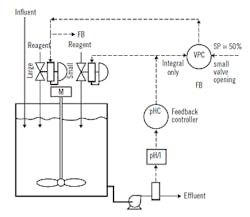
Another simpler, but more limited, method to extend valve rangeability is shown in Figure 2, where a valve-position controller (VPC) is used to drive the larger valve while the pH controller drives the smaller one. The VPC compares the output of the pH controller to its own setpoint (of 50%) and moves the larger valve slowly to that setting. The VPC action is integral-only and the contoller must be provided with external feedback to prevent windup. In this system, short-term control is provided by the VPC throttling the small valve to keep it at 50% opening, while the feedback controller (pHC) sets the bulk of the reagent flow as long as it's within the range of the large valve.
At times when the total load is under the minimum flow of the large valve, the VPC will drive the larger valve closed. This may bump the pH when the load rises and the large valve starts to open to its minimum flow. Also, this system may not be fast enough to cope with sudden load changes that require reagent flow changes outside the range of the smal valve.
When wastewater pH can vary on both sides of neutral, then acid and base valves must operate in sequence. The acid valve will throttle between 50-100% of the controller output, and the base valve will throttle from 50% to 0%. Both valves must fail closed, and therefore, the base valve requires a reverse-acting positioner.
Figure 2: Another method to extend valve rangeability uses a valve-position controller (VPC) to drive the larger valve, while the pH controller drives the smaller one. The VPC compares the pH controller output to its own setpoint (of 50%) and moves the larger valve slowly to that setting. Short-term control is by the VPC throttling the small valve to keep it at 50%, while the feedback controller (pHC) sets the bulk of the reagent flow when it's within the range of the large valve.
Smart digital positioners are recommended on all valves used in controlling pH, whether sequenced or not, because only they combine speed with the required elimination of deadband, and can also be individually characterized if necessary.
Béla Lipták
[email protected]
Q: Who invented the Coriolis flowmeter?
As an instrumentation and control training instructor in a French institute (Institut de Régulation et d'Automation, or IRA), I am curious to know who invented the Coriolis flow metering principle. I'd like also to have the detailed equation which yields the mass flow rate from the measured time shift between the two pick-up sine waves.
Philippe Trichet, Technical Expertise Project Leader
[email protected]
A: Patent number US4491025 A.
Alex (Alejandro) Varga
[email protected]
A: James Smith invented it. He sold it to Micro Motion, an Emerson company, about 35 years ago for about $100 million. Previously, he worked at a company that made precision weighing scales and wondered how he could apply what he knew to measuring the mass flow of fluids.
I visited him at his huge ranch in Montana on the Canadian border. He has a massive hangar with vintage WW II warplanes. He is an extremely innovative and generous man who has done a lot to help wounded vets.
The Coriolis invention of Jim Smith is the greatest innovation in the flow metering field in the past 50 years.
John Olin, chairman, Sierra Instruments Inc.
[email protected]

Leaders relevant to this article:
