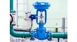
Valve specification begins with the control loop, which includes the transmitter that forwards signals to the computer, positioner and its actuator. The control valve assembly consists of the actuator that opens and closes the valve, positioner that converts electric signals to pneumatic signals, and valve that partially obstructs flow to control a process parameter.
Valve anatomies
Up close, the positioner has a lot of moving parts, but it's typically a box mounted directly to the valve; it hooks up to the instrument air supply; supplies the actuator with air to control valve position; and often provides diagnostic information for the valve.
Meanwhile, the actuator receives a pneumatic signal from the positioner; amplifies the signal to overcome process pressure; and provides a safe failure direction in the event of signal loss, such as "open, closed, last." The two main types of actuators are:
- Diaphragm actuators, in which air pressure acts on a diaphragm with high surface area, and it's opposed by a spring that dictates fail direction. They're low-friction; provide a fast response to small changes (which account for most changes in a process); and have a longer response time for larger changes. They're the process industry standard.
- Piston actuators, which are selected when more thrust or greater stroke length is needed. They can be single-acting or double-acting. While double-acting provides better thrust and is more precise, it also requires a volume tank that needs maintenance, as well as a locking mechanism to fail in any position other than last.
The valve body's primary features includes the process connections, such as flange, NPT or wafer, which join it to the pipe; stem that moves the final element to partially obstruct process flow; and vena contracta, which is the point where the stream has the lowest surface area. The two main design families are:
- Rotary valves are modulated by a rotating stem, and are generally classified by the design of the closing member. They're full port and free draining, have high capacity for a given line size, and have a narrower optimal control range. They include butterfly, v-notch ball and eccentric plug valves.
- Sliding stem valves are modulated by moving the stem in a linear fashion. They have lower capacity for a given line size, and a wide control range. Their two varieties are balanced and unbalanced. Unbalanced moves against process pressure, and is easier to seal. Balanced uses holes to transfer pressure, and doesn't require as much force from the actuator, but requires a seal between the plug and the cage.
The data sheet
So, how do users communicate what valve technology they need? They use the data sheet. Our examples here use the ISA's format, but vendors also provide data sheets. And, though most data sheets have a similar structure, and many client sites have a preferred format that supersedes the ISA's requirements.
We recommend filling out a data sheet by answering the well-known riddle, "How do you eat an elephant?" One bite at a time. This means separating the data sheet by sections, and tackling each section individually. The typical sections are:
- Revision block that lists people or groups with information, lists history of the instrument, project history and changes over time. Best place to start because it's information you already have.
- Process data is a thumbprint of the application, and should be filled out by a process engineer or someone else who knows the process. It provides information to determine chemical compatibility, physical design specifications and sizing. More information is better! For example, if you're sizing for three flowing conditions, each needs a unique flow, inlet and outlet pressure. Ask questions that might not be apparent about the section, such as is the service dirty/corrosive, erosive, toxic or flammable? You can always remove unnecessary information when the data sheet is issued!
- Manufacturers and valve type includes picking a manufacturer from the site's approved manufacturer list; consider the body style (rotary or sliding stem) that suits the application best; and find a model type that suits the design temperature, shutoff pressure, and line size of your application.
- Actuator is generally selected based on valve type, and sized by vendor. A hydraulic calculation is used based on valve requirements and minimum available air pressure. A safety factor of 10%, 25% or 50% is usually included based on how likely the service is to clog the valve or inhibit valve movement.
- Positioner is chosen by input type and desired diagnostics. High performance is often available for applications where response time is critical.
- Materials include two types: external and trim. Requirements for trim are more stringent as small changes to these surfaces can drastically affect performance of the valve.
- Notes is a great place for information that doesn't fit in the body of the data sheet. This can include testing and certification requirements or references to other relevant documents. However, avoid installation notes here, or specifications that won't be provided to the vendor.
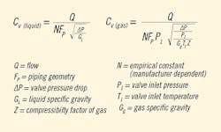
Figure 1: Flow is not all that defines flow capacity (Cv) required by process conditions, but these equations do. Most manufacturers supply sizing software, users enter their process variables, and the software outputs the Cv for each flow condition. Users then look at the flow Cv curve to pick and approximately sized valve. Source: Ambitech
It's also important for all valve specification team members to communicate needs and expectations clearly, as real specifications generally require compromises in certain areas to optimize performance.Sizing theory
Flow is not all that defines flow capacity (Cv) or contributes to selecting the right valve. It's only part of the overall puzzle. Cv defines flow capacity required by process conditions (Figure 1).
Most manufacturers supply sizing software, users enter their process variables, and the software outputs the Cv for each flow condition. Users then look at the flow Cv curve to pick an appropriately sized valve. The curve plots Cv travel % for a given value, which is different for each valve, and is supplied by most vendor software.
Placing the operating points at favorable control points on the Cv curve is important. Plus, characteristics vary by valve type.
What could go wrong? Plenty
The three primary issues that can adversely impact valves and specifying them are material such as corrosion and erosion, capacity such as high and low Cv requirements, and phase change such as flashing, cavitation and two-phase flow.
Corrosion is the gradual destruction of a material due to chemicals. Risk factors in the process include process fluids and high temperature, while common corrosion vectors include acid/base reactions, hydrogen embrittlement, sulfide stress cracking and stress corrosion cracking. Solutions can be found by: consulting a material compatibility table; consulting a materials expert in your organization; investigate other applications for a similar service; and considering a corrosion-resistant alloy such as Hastelloy, Monel or titanium-based alloys.
Erosion is the gradual destruction of a material due to physical stress. Risk factors include solid particulates, especially those with high particulate size/hardness, high velocity and phase changes. Erosion causes damage to wetted parts and plugging of small spaces. Solutions include: harden wetted parts with martensitic alloys or stellite facing, install a filter upstream; avoid restricted trims; use a rotary design to maximize surface area and minimize path changes.
High Cv applications have high throughput with low pressure drop, are often found in pump suction or as an add-on to a system that's already hydraulically stretched. The solution for high Cv applications is to have the largest vena contracta possible, and use an open port, which usually means employing rotary valves.
Low Cv applications have low throughput and high pressure drop, are often in injection or purge applications, or in level settings on highly pressurized vessels. The solution for low Cv is to use the smallest vena contracta, often to employ restricted trim, and recognize these applications are sensitive to plugging and that there are limited anti-cavitation options.
Turndown = Cv max / Cv max are addressed by solutions available for high or low Cv applications, though it's difficult to do both. Talk to the expert users of the process, and find out what's most important to them if you find no valve exists that can control at both the minimum and maximum points.
Phase changes include flashing, cavitation and two-phase inlet flow. These involve big physical changes that can cause a lot of stress. Phase change risk factors include: when the initial phase is liquid, vapor pressure that's close to inlet or outlet pressure, or pressure drop that's a large percentage of inlet pressure. When fluid moves through a valve, flow remains constant through the system.
Flash occurs when flow goes in as a liquid and out as a vapor, which can cause a lot of damage due to hydrodynamic stress. While there's no way to reliably predict the extent or rate of damage, reducing velocity of the stream can help, as can redirecting the impact to non-valve surfaces, and hardening all control surfaces. Frequently, this means angle valves or rotary valves in reverse flow.
Cavitation is a liquid-vapor-liquid phase change that can be very violent. Solutions include beefing up with restricted or hardened trims like stellite, which can mitigate damage, but won't prevent it. Users can also deploy special anti-cavitation trims to prevent cavitation, such as: cage type with small holes, though they can plug and may need service, or notch type that uses a series of notches to redirect flow. The idea is to stage the pressure drop, so cavitation doesn't occur, but this also means restricted flow profiles and minimum flows.
Two-phase flows come in two types: gas-liquid that contains two different components in two phases such as air and water, and vapor-liquid that contains one components in two phases such as steam and water.
No method exists to analytically calculate Cv in a two-phase system. Consequently, the first rule for sizing a control valves for two-phase flow is—don't!
However, if you have to size for two phases, then think happy thoughts, ensure you have flow data on both phases, approximate the Cv by adding the Cv of each phase, and in vapor-liquid phases, include overcapacity to account for possible process upsets.
About the author
Eric Lofland is senior engineer in the Instrumentation and Controls Dept. at Ambitech Engineering Corp., which is a Zachary Group company. He can be reached at [email protected]

Leaders relevant to this article:
