Application fundamentals of safety solenoids

Solenoid valves are among the most common components of safety systems. They’re commonly used to vent a valve actuator to move the associated valve to a safe state. Most are relatively simple electromechanical devices with mature, proven designs that can provide reliable service in safety instrumented or safety interlock systems when properly selected and applied. Advances in technology have also brought us smart devices that can provide solenoid functionality but with enhanced testing and communication capability.
For simplicity in this article, “SIS” is used as a generic term for both safety instrumented systems and safety interlock systems; “solenoid” also refers to “solenoid valve;” and a ”SIS valve" or "valve” are used as generic terms that can refer to any valve used in an SIS. In addition, there are three typical solenoid signals and motive forces (electrical, pneumatic and hydraulic), but again for simplicity in this article, we'll refer only to the electrical signals and pneumatic motive force, even though other signals and motive forces can be substituted.
SIS solenoids typically move a valve to a safe state by venting pressure when a de-energize-to-trip (DTT) circuit is used, or by applying pressure when an energize-to-trip (ETT) circuit is used. The most common SIS solenoids are the three-port, dual-action (3/2), normally closed (NC) variety used in DTT circuits that vent the valve’s motive force off the SIS valve’s actuator, causing the valve to provide the desired safety action. A DTT example of a solenoid with a manual reset is shown on the left in Figure 1 with a commonly used symbol for a 3/2 NC solenoid. The right-hand diagram in Figure 1 shows an alternative 3/2 solenoid symbol commonly used with spool-type solenoids.³
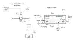
Figure 1: A DTT example of a solenoid with a manual reset is shown on the left with a commonly used symbol for a 3/2 NC solenoid. The right-hand diagram shows an alternate 3/2 solenoid symbol commonly used with spool-type solenoids.
There are a wide variety of solenoid construction styles. The three general types are the plunger or poppet style, where the plunger is directly moved using an electromagnetic solenoid to control the air flow through the solenoid. The second type uses a diaphragm to control the air flow through the solenoid. The third type features a cylindrical spool with ports move to control the air flow through the solenoid. The electrically actuated solenoid is by far the most common. Pneumatic or hydraulic solenoids are sometimes used to move valves, but are typically actuated by the SIS logic solver using a separate electrical solenoid.
Solenoid safety/risk calculations
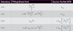
Table I: This table shows the probability of failure on demand average (PFDavg) values and spurious trip rates for solenoids used in common redundancy configurations, starting with one-out-of-one, etc. Other key parameters include λDU = dangerous undetected failure rate, λSU = safe undetected failure rate, TI = proof test interval, and β = common cause factor.
When used as a component in a safety system, the probability of failure on demand average (PFDavg) and spurious trip rate (STR) of a solenoid assembly are key design parameters. The simplified equation versions of the low-demand PFDavg equations for common solenoid arrangements, which show the significant contributors to PFDavg and STR for solenoids, are given in Table I. (For more detailed PFDavg/STR equations, please see Reference 6.)
The beta (β) or common cause factor’s contribution is included because it can significantly contribute to the PFDavg calculation for redundant configurations. For example, Asco recommends a β value for their solenoid valves of 5%.¹ The uncertainty of the calculation parameters is also a key factor in determining the confidence in the PFDavg calculation.6
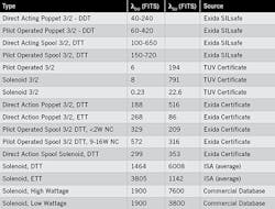
Table II: The dangerous undetected and safe undetected failure rates for solenoids, reported here in failures in time, or FITS (per billion hours), can vary substantially.
For simple solenoid arrangements, it's normally assumed that solenoid failures will be detected when proof tested and the mean-time-to-repair/restore (MTTR) doesn't significantly contribute to the PFDavg/STR. More sophisticated solenoid arrangements with on-line testing and repair may add consideration of the MTTR contribution. Since the proof-testing coverage (PTC) for testing solenoids can typically approach 99%, the PTC typically doesn't significantly contribute to the PFDavg.1
The dangerous undetected and safe undetected failure rates for solenoids can vary substantially as shown in Table II. Some of the claims of failure rates stretch one’s imagination, so be careful what you accept. The failure rates used for plant applications should be in line with plant maintenance and practical industry experience for solenoids, and once in service, should be treated as a proven-in-use device. The exida SILSafe failure rates are also provided for solenoids in Table II. These rates are what exida’s data indicates are expected ranges for failure rates for solenoids in process industry applications.
It should also be noted that the values in Table II are random failure rates, which are considered to be constant during the useful life of the solenoid. Such failure rates are those in the bottom of the “bathtub” curve shown in the “useful life” area in Figure 2.
A solenoid valve, however, has both electrical and mechanical parts. The constant failure rate assumption may apply to the electrical components, but not so much to the mechanical components (spring, plunger, diaphragm, o-rings, seals, spool, surface-to-surface contact, etc). It's proposed from practical experience that the dangerous failure rate for devices that contain mechanical parts is that the failure rate actually contains both a random factor and a time-dependent factor:
λDtotal = λDrandom + λDtime dependent
Once time-dependent failures start increasing the failure rate, the standard PFDavg calculation may not be as valid as service time increases. However, current industry practice is to use the constant random failure rate in the calculation of PFDavg for the design of electromechanical (e.g., solenoids) and mechanical devices (e.g., valves). The takeaway from this is that due to the lack of data on failures that are time-dependent, extra care should be taken in designing long-test-interval SIS systems.
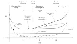
Figure 2: The failure rates listed in Table 2 are random failure rates, which are considered to be constant during the useful life of the solenoid—after an elevated period of infant mortality and before failures due to wear-and-tear begin to escalate.
IEC 61511, clauses 11.9.3 and 16.2.2, require collecting reliability data to validate data used in designing the SIS. This is where collecting failure data for solenoids comes into play, which can allow us to better understand our failure rates and what numbers to use in our calculations for different applications.
Unfortunately, collecting failure rate data in a test interval is typically not done and can be difficult, though some correlation may be possible based on failures in long test intervals vs. short test intervals and from failures detected from on-line testing. This can potentially provide useful data to allow us to design better SIS systems—particularly for long-test-interval systems. Any SIS failure should be considered equivalent to a near miss and the failure mechanisms forensically investigated.
As a result, at this time it's difficult to determine how much the failure rate of a solenoid could increase due to the length of time in service other than anecdotal evidence that mechanical devices tend to fail more frequently the longer that they're in service.
Researchers at exida2 indicate that stiction (a combination of the words stick and friction, and a measure of a valve’s tendency to get stuck in place) increases with the length of time the contact surfaces are stationary with respect to each other, and reaches a maximum at about 275 hours (~11.5 days). Given this number, one might expect a lot of solenoid failures at any normal level of proof-test intervals, which doesn't seem to be the case. The writers also suggest periodic testing of solenoids to improve the reliability of the solenoid system, starting weekly, and adjusting the test interval based on test data. Since stiction and other causes of stuck solenoids tend to increase with service time, on-line testing of solenoids and partial-stroke testing of solenoids and SIS valves should be considered good engineering practice.
A fair number of solenoid manufacturers feature models that are third-party qualified (by exida, TÜV and others) for SIS service. While approval isn't required by IEC 61511-1, it's good engineering practice to specify solenoids approved to meet IEC 61508—especially if an adequate level of local failure data and plant maintenance experience isn't available to qualify a proven-in-use solenoid. Approved devices have several important documents that should be reviewed before selection and design of the solenoid assembly. These are the approval certificate, approval report, the device’s safety manual, and if available, the solenoid failure mode and effects diagnostic analysis (FMEDA). The approval certificate typically has the failure rates, the systematic capability (SC), and the hardware fault tolerance (HFT), while the approval report, safety manual, and the FMEDA will typically include useful life, recommended proof tests and any limitations that can affect the design. There can sometimes be “gotchas” in these documents that can significantly affect design, operation, and maintenance requirements to meet the approval requirements, so a careful review of them is highly recommended.
SIS solenoids are considered to be simple Type A devices and are typically approved for SC of three, and are safety-integrity level (SIL) 3 capable with appropriate redundancy to meet the required architectural constraints for SIL 2, HFT = 0; and for SIL 3, HFT=1. Care should be taken when evaluating any claim of a single device meeting SIL 3 requirements. Also, note that some approvals only apply to the NC version of the solenoid and don't apply to the normally open (NO) versions.
Other design considerations
When selecting a solenoid, key parameters include the solenoid’s upper and lower ambient temperature specification, the solenoid exhaust rate capacity (which affects valve response time), area classification, wattage, materials of construction, failure rates and useful life.
Designers sometimes worry about the upper temperature environment but fail to consider that the lower temperature rating can get them into trouble. Solenoids must be selected to meet the plant’s worst-case ambient temperature extremes, and some solenoids have a lower temperature specification that's within the expected ambient range for some locations.
The upper service temperature should be selected with an adequate margin. A common rule of thumb is that the life of an electrical/electronic device is halved for every 10 ºC rise in operating temperature. And, the cooler an electrical/electronic device operates, the longer it will last. Lower wattages typically operate at low temperature, may have a longer useful life, and be less prone to spurious trips. However, they may not have enough power to overcome stiction forces. See Reference 5 for additional information in this area.
In areas where insects may build a nest in the exhaust port of the solenoid, a bug screen should be installed, which is generally a good practice.
The common-coil voltages are 24 VDC and 120 VAC. 120 VAC is typically used when more power is required, but can have a higher inductive kick that may reduce the solenoid coil and PLC output life if surge protection isn't adequate. Many SIS logic solvers are better configured to use 24 VDC, and may require additional interposing relays to use 120 VAC.
The valve assembly materials should be suitable for the motive force used and the external corrosive environment. Solenoid venting capacity is also a concern, particularly for big valves. Most standard solenoids have a range of sizes and capacities, and models with larger venting capacity are available. However, digital valve controllers, smart solenoids and smart positioners come in limited sizes, and venting capacity to achieve desired response time should be verified as they aren't always clearly stated in their specification literature.
Useful life is a key parameter for any device because it's where the random failure rate is considered constant and the standard PFDavg calculations are considered valid. At the end of useful life, the wear-out phase is considered to start, and the failure rate is no longer considered constant. The Asco manual on solenoids in SIS lists solenoid useful life as three to 10 years.¹ Review of several FMEDAs for solenoids gives the useful life for a solenoid as 30,000 hours for the coil and 10 years for the solenoid valve assembly. Failure of the coil for DTT systems typically results in a safe failure, however, startup after a spurious trip can increase the risk to the plant.
A well-designed solenoid system can extend the useful life of the solenoid and provide long-term reliable service. This is where local collection of failure rates and failure mechanism/mode data is important to determine what the replacement policy will be for solenoids and other devices at the end of their specified useful life. FMEDA useful life predictions are typically based on having clean air and an ambient temperature of 40 ºC (101 ºF). The solenoid also must meet the area classification; have adequate enclosure to protect against the environment (typically NEMA 4 as a minimum); and should consider surge protection on larger solenoids and when solid-state logic solver outputs are used.
Of the two trip philosophies, de-energize-to-trip is by far more common, generally safer and easier to design than energize-to-trip configurations. However, if you wish to use an ETT system, you must comply with 61511-1, Clause 11.6.2, which requires that ETT circuits shall have means to ensure circuit (coil) and power supply integrity. It should also be noted that double-acting safety valves are ETT systems because they require that motive force be applied to one side to the valve to move the valve to a safe state, and solenoids in these systems may have to meet the ETT requirements.
Redundancy is also a design consideration, and the common redundancy schemes are 1oo2, 2oo2 and 2oo3. In hydraulic systems, 2oo4 redundancy schemes are sometimes used.
The 2oo2D (for diagnostic)/1oo1HS (for hot standby), 2oo2, 1oo2, and 2oo3 solenoid redundancy schemes are available in industry as packaged or OEM equipment with online testing capabilities.
Another example of a redundant solenoid arrangement is the Norgren IMI-Herion RVM (redundant valve manifold), which provides a configurable redundancy scheme mounted on one manifold (1oo2, 2oo2, 2oo3). These systems are commonly rated to SIL 3, and have pressure sensors and manual bypasses that allow online testing and maintenance. The systems are not inexpensive, and typically require a higher level of support than simple solenoids, but can provide enhanced testing ability, and can be easier to apply than roll-your-own systems. Careful review of the approval documents and their safety manual should be done to ensure they're properly applied and the approval requirements are met.
Smarter solenoid systems
Basic solenoids are simple, dumb devices, but the industry has come up with several types of smart/intelligent devices that can provide solenoid functionality and/or solenoid online testing. These devices typically provide a range of enhanced online testing capabilities (e.g., partial-stroke testing) and the ability to collect and store test data for the solenoid and the associated valve assembly. Examples of these include Emerson's DVC-6200SIS digital valve controller, Neles' ValvGuard VG9000 intelligent safety solenoid, Norgren's IMI Precision Engineering ICO4-PST/SIS smart solenoid valve, Westlock's Epic-2 intelligent valve position transmitter, Sampson's Series 3730-3 smart positioner, and Schneider Electric's Foxboro PST smart positioner.
Some things to be careful of are venting capacity and the downstream use of quick exhaust valves and other devices other than the SIS valve. The potential use of downstream devices should be reviewed with the smart device’s supplier. While these smart devices aren't inexpensive, they bring a lot to the table, particularly in a long-test-interval SIS. However, they require a higher level of support than standard solenoids. The use of these smart devices for all SIL 1 applications may be somewhat cost prohibitive if you have many of them. For SIL 2 and SIL 3 systems, these smart devices may be a good fit depending on the application.
The use of these smart devices, particularly for long proof-test intervals can improve the reliability of your SIS by periodically cycling the solenoid and the collection of test data from both partial and full stroke tests. This can give users a better understanding of what's occurring in their solenoid valves and SIS valve assemblies to allow for validation of current SIS design practices and improve designs where needed.
Manual reset is also a common option. The manual reset won't typically allow a reset of a solenoid until the SIS logic solver has energized the solenoid signal, which indicates the SIS thinks it's safe to manually reset the solenoid. This option is commonly used on furnaces and other applications, where it's desired for the operator to verify that field conditions are safe prior to reset.
Solenoids are simple devices but play a big part in the SIS and its reliability, so proper selection and design is very important to the success of the SIS. Smart technologies have enabled more sophisticated devices that provide the ability to test solenoids online, which may be advantageous in long-test-interval SIS and other applications. Whether the smart devices will replace the standard solenoid valve remains to be seen, but I believe the standard solenoid will long be with us due to its simplicity, mature design, ease of support, flexible size and lower cost. They can provide reliable service when properly applied.
References
- “Asco Solenoid Valves used in Safety Instrumented Systems,” I&M V9629R2
- “Improving Reliability & Safety Performance of Solenoid Valves by Stroke Testing,” Loren L. Stewart, Julia V. Bukowski, Ph.D, & William M. Goble, Ph.D., exida
- Asco Pneumatic Symbols, http://www.asconumatics.eu/images/site/upload/_en/pdf1/00482gb.pdf
- “Effective Compliance with IEC 61508 When Selecting Solenoid Valves for Safety Systems,” by David Park and George Wahlers (Asco whitepaper)
- “Optimizing Power Management in Solenoid Valves,” Stephen Glaudel (Asco whitepaper)
- ISA TR84.00.02, “Safety Integrity Level (SIL) Verification of Safety Instrumented Functions.”
About the author
Frequent Control contributor William (Bill) L. Mostia, Jr. PE, principle engineer, WLM Engineering Co., can be reached at [email protected].
