Two valves provide wide rangeability
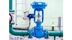
Figure 1: This configuration, where a high pressure switch (HPS) set at 65% and having a 30% differential is sequencing two equal percentage, 50:1 turndown control valves and can provide an overall turndown of 1,000:1.
A2: It's not always possible to have a completely bumpless transfer when you have multiple outputs. However you can minimize the "bump" by using ramp functions. In this case, you ramp to close one valve and ramp open the other one, for instance, over 20 seconds. (I'm assuming that the two valves are the same size.)
There will be two analog outputs that are switched to the PID controller. Check with the configuration parameters. When you switch there should be some initialization settings that can set these ramp times. This isn't an unusual configuration, and a modern DCS should accommodate this situation.
Also, check with operations on how they want to switch over. The operator may want to do this manually by slowly opening the bypass valve and letting the controller close the main valve. If you have two PID controllers (one for each valve), you can easily do this. There are some more options available to you with separate controllers. Try some ideas out.
Simon Lucchini, CFSE, MIEAust CPEng (Australia)
Chief Controls Specialist
Fluor Fellow in Safety Systems
[email protected]
A3: This is frequently the situation when the original control valve was greatly oversized. A new, much smaller control valve is installed to make the control loop stable and responsive. Overly large control valves will typically operate over a small fraction of valve opening, and may not be able to achieve a stable control loop. Smaller control valves will then operate over a much larger range of valve motion, enabling smooth control loop response. While removing the large control valve is the logical solution, many plant operations may not agree with this removal, so installation of a smaller control valve in a bypass line is a compromise, and the large valve isn't used. Nothing needs to be done in this case.
If the two valves are used for different products or production rates, then the control loop gain is changed when the alternate control valve is used. This will require that the PID control loop tuning be changed when the valve is switched. There is nothing to be done about bumpless transfer from manual to auto, but the tuning constants will need to be changed when the transfer switch position is changed.
Richard H. Caro, CEO
[email protected]
A4: In the absence of sufficient background information, I assume following points:
- Both valves have the same Cv and the design basis is 2 x 100%, meaning that either of the valves can meet the maximum flow demand.
- Isolation valves are provided on the upstream and downstream sides of each control valves and are fully open.
Now, let’s say valve A and valve B are at 50% and 0% open, respectively. (Valve A is online and valve B is fully closed). When the operator switches valves, valve B shall linearly ramp up to open and A will linearly ramp down to close. Both ramp slopes will be same. This means when B opens 10% gradually simultaneously A will close 10% (40%). This will ensure in each step flow will remain same.
D. Guha
[email protected]
A5: From what I understand, valve B is a bypass valve; and one would take it in line only when valve A has a problem and needs maintenance. In that case, one solution would be to take the controller on manual, keep the output at last value, and switch over the valve selector from A to B. This will not be bumpless though.
Another solution would be to have two soft controllers, one for each valve, without a selector switch, and keep both controllers in auto, and then in the field, start closing isolation valves for valve A and opening isolation valve of valve B—slowly and simultaneously.
H. S. Gambhir
[email protected]
A6: Your DCS or PLC should have standard tracking options to allow the configuration of a bumpless transfer between valves. Should the valves have different Cv, the PID tuning parameters may have to be revisited.
Sigifredo Nino
Process Control Consultant
[email protected]
A7: Without getting into details of the programming development package you're using, the easiest thing to do is take your PID block output through the status of the selector switch. Based on status of that switch, PID block output will either be sent to %AQ for valve A or %AQ for valve B.
What that means is, as soon as the status of the switch changes, output will drive the respective valve. Keep in mind though that valve B when called after stable operation on valve A will have slightly more lag to reach that % opening, and so your loop will not be steady for some time.
Again, this is very preliminary and basic based on information you provided.
Hiten A. Dalal PE PMP
Senior Automation Engineer
[email protected]