Here is our finale just in time to serve as a momentous process control gift for the Holidays. Just don’t try to re-gift this to anyone unless they are into the automation profession or you big time.
(21) Misuse and Missing Use of Setpoint Filter. The use of a setpoint filter on a secondary loop setpoint will slow down the ability of the primary loop to make a correction for changes in load to or the setpoint of the primary controller in cascade control. For this reason, there has been a general rule of thumb that a setpoint filter should not be used on secondary controllers. However, as with most rules of thumb there are important exceptions derived from a deeper understanding. The setpoint filter on the secondary loop does not interfere with the ability of the secondary loop to reject disturbances and to deal with nonlinearities within the secondary loop that is often the most frequent and important role. If the setpoint filter is judicially applied so that it is less than 10% of the primary loop dead time, the effect on the ability of the primary loop to reject disturbances originating in the primary loop is negligible. The use of a judicious setpoint filter can ensure there are no temporary unbalances from changes of multiple flows under ratio control by enabling all the flows to move in concert. This is critical for reactant flows and the inline mixing of any flows. Often this unbalance was prevented by tuning the secondary flow loops to have the same closed loop time constant. Unfortunately, this forces the tuning of loops to be as slow as the slowest or most nonlinear flow loop. This detuning reduces the ability of the other loops to deal with their pressure disturbances and nonlinearities of their installed flow characteristics. Also, the use of setpoint rate limits that are different up and down gives directional move suppression to provide a fast approach to a better operating condition and a fast getaway to prevent undesirable operating point in the process variable (PV) or manipulated valve position. This is important to provide a fast opening and slow closing surge valve for compressor control, to optimize user valve position to improve process efficiency or maximize production by a valve position control, and to prevent oscillations across a split range point. For primary loops, a setpoint filter time equal to the reset time is the same as a PID structure of Proportional and Derivative on PV and Integral on Error (PD on PV, I on Error) so that the setpoint and load response are the same. The addition of lead time to the setpoint that is about 25% of the setpoint filter where the filter is lag time of a lead-lag block enables a faster setpoint response.
(22) Choosing and Achieving Level Control Objective. We are increasingly becoming aware that level loops are tuned too aggressively causing rapid changes in the manipulated flow upsetting downstream unit operations. The solution for level loops that need loose control is not to simply reduce the level controller gain because this can cause slow rolling oscillations. The tuning objective is to so minimize the transfer of variability of level to the manipulated flow and is more often stated as the maximization of the absorption of variability. The solution is to first increase the reset time dramatically, like one or two orders of magnitude, and then decrease the PID gain so that the product of the PID gain and reset time is greater than twice the inverse of the integrating process gain whose units are %/sec/% (1/sec) as discussed in Mistake 2 in Part 1. For surge tank level control, the objective is obviously maximization of absorption of variability. This objective has gained such popularity that the cases where the level controller must be tuned tightly are not recognized and addressed. In fact some may say there are no such cases and that feedforward control can take care of providing tighter level control when needed. There are exceptions. The biggest one that comes to mind is the distillate receiver level controller that manipulates reflux flow. Tight level feedback control achieves internal reflux control where changes in column top temperature, particularly from blue northerners, causes a change in overhead distillate flow and hence distillate receiver level that results in a correction of manipulated reflux flow in the direction to minimize the disturbance. Another case is where tight residence time control in continuous reactors provides enough time to complete a reaction but not so much time as to cause side reactions or polymer buildup. A change in production rate must result in a change in level setpoint that must be reached quickly by tight level control so that residence time (level/flow) is as constant as possible. A similar concern may exist for continuous crystallizers. For multiple effect evaporators, changes in discharge flow from the last stage to control product solids concentration must be translated to changes in feed coming into each stage by its level controller to affect product concentration. There are similar requirements whenever an upstream flow is manipulated to control a level, such as a raw material makeup flow to deal with changes in a recovered recycle flow. While feedforward flow and ratio control can help, good level control deals with the inevitable errors that cause unbalances in stoichiometry.
(23) Misunderstanding of Load Disturbances. There is a huge disconnect in the literature and what really happens in a plant in terms of the supposed location of a disturbance. The literature and consequently many tuning methods and new algorithms supposedly better than PID are based on the disturbance being on the process output downstream of time constants and dead times in the process and even in most cases ignoring any time constants or dead times in the measurement. This view is convenient for thinking model predictive control and internal model control are best for disturbance rejection and that tuning for setpoint changes is sufficient since a disturbance on the process output is as quick as a change in setpoint. The reality is that nearly all disturbances occur as a process input and are delayed by process dead times or slowed by process time constants. For lag dominant processes, this recognition is particularly important and is the basis of switching from self-regulating tuning rules where lambda is a closed loop time constant for a setpoint change to integrating process tuning rules where lambda is an arrest time for rejection of a load disturbance on the process input. Of course there are a few exceptions where the disturbance is on a process output that would benefit from a larger reset time but this can be identified by tuning the controller for a setpoint response. Also, when in doubt a larger reset time is always a good thing to try since integral action is destabilizing. More proportional action can be stabilizing as discussed in Mistakes 2 and 3 in Part 1.
(24) Missing Automated Startup. Often loops cannot be simply put in automatic for startup.The controller approach to setpoint is often not as smooth and consistent with other controllers approach to setpoint. Often the operator manually position valves to get the process to a reasonable operating state before going to automatic control. The best practices of the best operators can be automated and implemented with much better timing and repeatability enabling continuous improvement by better recognition of what is left to be addressed. If operators say the situation is too complex or conditional on their expertise to be automated, it is even a greater opportunity and motivation for automation. For much more on how procedural automation can be used for startup and dealing with abnormal situations, see the Sept 2016 Control Talk column “Continuous improvement for continuous processes”
(25) Missing Ratio Control. Nearly all process inputs are flows that have a specific ratio to each other for a unit operation as seen on a Process Flow Diagram. The simple use of ratio control is inherently powerful where a “leader” flow is chosen that is often a major feed flow and the other flow controller setpoints designated as “followers” are ratioed to the “leader” flow controller setpoint. If the flows need to work in concert with each other, a filter is applied to each flow setpoint including the “leader” flow for reasons noted in Mistake 21. The actual ratio must be displayed for the operator based on measured flows and the operator must be given the ability to change the ratio for startup and abnormal operating conditions via a ratio controller for each “follower” flow. The ratio often has a feedback correction by a primary temperature or composition controller output. For plug flow volumes, conveyors and sheet lines, the feedback correction changes the ratio setpoint. For back mixed volumes, the feedback correction biases the ratio controller output. For more on ratio control, see the 1/31/2017 Control Talk Blog “Uncommon Knowledge for Achieving Best Feedforward and Ratio Control”
(26) Misleading response time statements. The statements of response time have no value unless a percentage of the final response is noted. For linear systems, the 63% response time is the dead time plus one time constant. The 86% response time often used for valve response is the dead time plus two time constants. The 95% and 98% response times are the dead time plus three and four time constants, respectively. Waiting for the 98% response takes a lot of time making the test vulnerable to changing conditions and disturbances. For large distillation columns, it could take days to see a 98% response.
(27) Not knowing the dead time to time constant ratio. The tuning and performance of a control loop for self-regulating processes depends heavily upon the dead time to time constant ratio. Most studies in the literature are for loops that are smart enough to include dead time have a dead time to time constant ratio between 2 and 0.5 that are termed “balanced” self-regulating processes. When the dead time to time constant ratio is much larger than 1, the process is termed “dead time dominant” and the reset time can be significantly decreased and PID gain should be decreased to reduce the reaction to noise and abrupt response due to the lack of a significant time constant. For more on these processes see the 12/1/2016 Control Talk Blog “Deadtime Dominance - Sources, Consequences and Solutions”
When the dead time to time constant ratio is less than ¼, the process is termed “lag dominant” and “near-integrating”. Integrating process tuning rules should be used that increase the reset time and PID gain to account for the reduced degree of negative feedback in the process. In the time frame of a major PID reaction (4 dead times), the process ramps and appears to be similar to an integrating process. The integrated absolute error (IAE) for all processes is proportional to the ratio of the reset time to controller gain. The peak error for “dead time dominant” processes approaches the open loop error (error if controller was in manual). The peak error for “lag dominant” processes is inversely proportional to the controller gain since the PID gain can be quite high dominating the initial response. For more on how the dead time to time constant ratio affects performance see the 7/17/2017 Control Talk Blog “Insights to Process and Loop Performance”
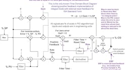
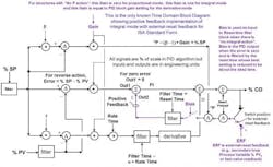
(28) Unnecessary crossings of split range point. The valve stiction and nonlinearity and process discontinuity is greatest when switching from the manipulation of one valve and stream to another. Once a controller output crosses a split range point, the tendency is to oscillate back and forth unless there is a predominant need for one stream versus the other. Putting a dead band into the split range point will cause oscillations if there are two integrators either due to integrating action in a process or from the integral mode cascade loop or a positioner. The best way to prevent an unnecessary crossing of the split range point is to put up and down rate limits on a valve or flow controller setpoint where the rate limit is slow in the direction of going back to the split range point if there is no safety issue. For cooling and heating, the movement toward heating across split range point may be slowed down for temperature control. For venting and gas inlet flows, the movement toward more inlet flow across split range point may be slowed down for pressure control. For mammalian bioreactor pH control, the movement toward adding a base across the split range point, such as sodium bicarbonate, is slowed down to reduce sodium ion accumulation that increases cell osmotic pressure and cell lysis. External-reset feedback to the primary PID of valve position or flow should be used so that primary PID (temperature, pressure or pH) does not try to change a valve or flow faster than it can respond. This is a great feature in general for cascade control and to provide directional move suppression for valve position control and surge control. For more on external-reset feedback see the 4/26/2012 Control Talk Blog “What is the Key PID Feature for Basic and Advanced Control” A corrected and improved block diagram in time domain for a PID with the positive feedback implementation of integral action for the ISA Standard Form essential for external-reset feedback is:
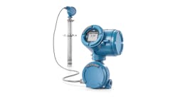
(29) Minimizing instrumentation cost. We get hung up on saving a few thousand dollars putting millions of dollars often at stake in terms of poor process performance and inadvertent shutdowns. A big mistake is allowing a packaged equipment supplier to choose the instrumentation since the supplier is seek to win the low bid contest. Similarly allowing purchasing to decide which instruments to buy is fundamentally bad. We need to take our knowledge about instrumentation performance and insist on the best even when the justification is not clear and pressure is put on to lower system cost. My cohort Stan Weiner would purposely increase the initial estimates for projects to give him the freedom to choose the best instrumentation. He favored inline meters such as Magnetic Flow Meters and Coriolis meters over differential head meters because of the better rangeability, accuracy, and maintainability and insensitivity to piping system. Similarly, for temperatures less than 400 degrees C, I use RTDs with “sensor matching” instead of thermocouples to reduce drift and improve accuracy and sensitivity by orders of magnitude despite a few hundred dollars more in cost.
(30) Lack of middle signal selection. The best way to avoid unnecessary shutdowns, eliminate the reaction to any possible type of single failure including a measurement stuck at setpoint, reduce the reaction to noise, spikes, and drift and provide intelligence as to what is wrong with a measurement is middle signal selection of three independent measurements. For pH this is almost essential. To me it is bizarre how multimillion bioreactor batches are put at risk from using two instead of three pH electrodes resulting in anybody’s guess as to which electrode is right. Some batches can be ruined by a pH that is off by just a few tenths yet engineers are reluctant to spend a couple of thousand dollars upfront not realizing that even if you disregard the cost of a potentially spoiled batch, the reduction in unnecessary maintenance more than pays for the extra electrode. For one large intermediate continuous process, the use of middle signal selection on all of the measurements used by the Safety Instrumented System (SIS) reduced the number of shutdowns from 2 per year to less than one every 2 years saving tens of millions of dollars each year. The risk of a disastrous operator mistake was also realty reduced because startup is the most difficult and hazardous mode for operations.
I could keep on talking but I think this is enough to start your “New Year Resolutions”. Hopefully, you will be better at keeping them than me.


