Misunderstanding 4-20mA signal loops

What you’ll learn in this article:
- Why many instrumentation and controls (I&C) technicians and engineers surprisingly struggle with core concepts such the 4-20 mA current loop
- How organizations that invest in fundamentals-based training can significantly improve personnel performance and reduce downtime
Greg: By identifying common critical knowledge gaps, organizations can better address training needs, and design improved systems, procedures and maintenance programs to boost team performance. Everyone involved in process automation and safety systems, including basic and advanced control practitioners and suppliers, needs this essential knowledge because measurements are the window into processes and these final elements affect the process.
Mike Glass, owner, Orion Technical Solutions, which specializes in instrumentation and automation training and skills assessment, says there are many unrecognized problems that severely deteriorate the ability of process automation and safety systems. He should know, as he holds ISA-certified automation professional (CAP) and certified control systems technician level III (CCST III) credentials, and has nearly 40 years of experience in instrumentation and controls (I&C) across multiple industries. His background includes roles as a nuclear reactor operator, and controls engineer and technical instructor, as well as more than a decade assessing and developing automation specialists and instrument technicians for offshore oil and gas operations in the Gulf of Mexico.
Mike, you’ve spent years conducting detailed assessments and training I&C and automation technicians and engineers. What have you discovered?
Mike: It’s been eye-opening and helpful for training people in the craft. Though I’ve been in the I&C field for nearly 40 years, I’m still surprised by both the prevalence and nature of the knowledge gaps (especially with fundamentals). The issues weren't isolated to niche or advanced topics—they nearly always stemmed from an inadequate understanding of core fundamental concepts. I became a believer in the adage that fundamentals are the key to success.
Greg: What do you think contributed to this situation?
Mike: The industrial landscape has changed dramatically over the past several decades. During manufacturing's heyday, companies invested heavily in comprehensive training programs, structured mentorships and formal development pathways.
Since the 1990s, we've seen these programs become systematically diminished as companies reduced costs. The apprenticeship model that once ensured knowledge transfer has largely disappeared. Today, many organizations forego formal development pathways for technical personnel.
It’s also harder to find highly trained technical school graduates. Companies are forced to select people who seem intelligent and are eager to learn, but companies don’t always have any path for eager personnel to grow and progress.
The consequences are increasingly apparent. Experienced professionals developed during an earlier era are retiring in droves, which seemed to accelerate since the pandemic, and this created a knowledge vacuum.
Greg: I saw this in specialty chemicals where I started in electrical and instrument (E&I) design and construction, and was responsible for calibrating, installing and commissioning E&I systems before migrating to engineering technology (ET). My perspective in Ask the Automation Pros – The Past and Future of Process Control discusses the loss of training and expertise I observed over my 55-year career.
How are organizations responding to skills gap challenges?
Mike: Most are struggling. For example, today’s early career engineers often receive minimal experience or developmental opportunities before being assigned significant responsibilities. Many find themselves siloed in narrow specialties or tasks without exposure to the bigger picture that would make them more versatile problem solvers.
Similarly, technicians often receive procedural type training—"do this, then this"—without learning underlying principles. They can follow steps, but lack the conceptual foundation to interpret procedures or effectively troubleshoot.
There’s no substitute for well-crafted developmental programs with a heavy investment in training, but many problems can be mitigated with targeted training focused on fundamentals. I've seen motivated personnel who came into the I&C world with little formal training learn the core concepts, and become exceptional performers within a few years. However, it only happens when they're taught the fundamentals and given opportunities to apply them.
Organizations often focus on equipment-specific training, while overlooking the basics. Learning about a particular transmitter model is valuable, but it’s far more powerful when built on solid instrumentation fundamentals. When someone understands core concepts, they can usually learn what they need from a manual. Without those basics, they're left to guess, part-swap or implement temporary fixes.
Greg: What’s the top gap you've observed in the I&C field?
Mike: If I had to pick a single item that underlies the biggest portion of the problems, it would be the 4-20 mA current loop. It's such a core concept in the field, yet surprisingly a common weakness. Other significant gaps include understanding smart instrumentation compared to older devices and misunderstanding instrumentation calibration programs.
Greg: Why do you feel it’s so important?
Mike: Nearly every analog instrument uses the 4-20 mA loop. Field transmitters, positioners, and variable frequency drives (VFD) implement the current signal loop for their I/O signals. It's everywhere, and we work with it almost daily.
Although the concepts aren't complicated, a large portion of engineers and technicians in the I&C field can't really apply the electrical concepts of the current loop to troubleshoot faults or understand procedures. They usually know how to measure current, but that’s about it.
I've seen this singular weakness cause problems in everything from safety instrumented systems’ (SIS) procedural mistakes to calibration errors to poor troubleshooting, where transmitters are swapped out due to signal path problems that users can't understand.
Interestingly, many managers are surprised their staffs, including experienced personnel, have significant weaknesses in this area. If an I&C manager doesn't have deep craft knowledge, it's easy to be fooled by someone who may legitimately believe they're highly skilled, but who has underlying weaknesses.
Greg: How do you gauge someone's overall knowledge of the 4-20 mA loop?
Mike: When possible, I use a bench setup with real equipment. If equipment isn’t available, I might sketch a basic current loop with a 24 V power supply and a transmitter, and ask them what voltage they'd expect across the transmitter terminals at 50% output with a typical 250-ohm analog input. The right answer is 21 V, based on 24 V—(0.012 A x 250 Ω) = 24 V – 3 V = 21 V—but I'm often surprised at how many experienced, confident techs or engineers immediately say 24 volts (Figure 1).

This isn't just theoretical. If someone doesn't grasp these basic voltage and current relationships, they'll struggle with understanding SIS high-/low-fault tests, and won't be able to troubleshoot challenging problems such as partial shorts due to moisture in junction boxes. They'll just keep replacing perfectly good transmitters or offsetting calibrations, while the actual problem remains.
Greg: Let's talk about loop-power requirements. What do people commonly misunderstand?
Mike: Many in the I&C field don't understand that if voltage on a 4-20 mA transmitter falls below its minimum required voltage, the output appears to saturate. Typically, the current seems to stop increasing at some value around 17-19 mA regardless of the transmitter target output level. I like to have them experiment with this during my training classes.They can adjust the voltage and a potentiometer in the loop to get a feel for the voltage and impedance relationships vs the information in the reference manuals.They can also watch the transmitter behavior in those conditions. It’s the best way for people to lock on to the concepts.
In short, the transmitter is as "on" as it can get, and there just isn't enough voltage to push higher current levels through the loop with all the resistance in it.
Greg: How would this voltage limitation manifest in real-world situations?
Mike: As an example, with 24 V and 500 ohms of loop resistance at 21.75 mA, you'd end up with 24 V – 5.4375 V – 5.4375 V = 13.125 V remaining at the transmitter.
That would be a problem for many transmitters, where the minimum voltage spec might be 14-16 V. For example, some commonly used modern GWRs need 16 V minimum to function (Figure 2).

Another issue is how HART communications behave when transmitters reach minimum voltage. HART communications become unreliable as you approach these minimums because the digital signal gets distorted due to transmitter saturation. This occurs because of how the HART signal is superimposed and centered on the 4-20 mA signal voltage. The available headroom goes away as it approaches voltage limits, causing distortion in the shape of the square wave, and making it hard for the modem to interpret.
Often, the HART communicator will suddenly go offline while technicians are calibrating or SIS testing after they command the output to a higher level. This can be perplexing to the untrained. It’s also tricky getting reconnected to the transmitter when this happens (try powering the transmitter down and recycling power). I've even heard of transmitters being replaced because of this problem.
New, smart transmitters, especially those with higher power requirements that were previously four-wire devices but are now two-wire, have notably higher minimum voltage specs than older, simpler transmitters. Many of these units are just under the line on voltage budgets when users have another device in the loop besides the analog input's 250 ohms.
Unless engineers are aware of these issues and apply these concepts and transmitter specs, they sometimes design these transmitters into loops where they simply can't work properly under all conditions (especially high-current levels and/or high-fault current conditions). I've seen this happen multiple times, particularly when there are additional loop components consuming the remaining voltage.
Greg: What field problems have you observed related to loop impedance?
Mike: I've encountered multiple scenarios where technicians were jumpering out non-incendive barriers (NIB) as a tribal knowledge "quick fix" for certain SIS transmitters to get past boot-up. In those cases, the transmitters perform low- and high-fault current tests during startup to ensure full operability. When they sense excessive loop impedance, they revert to a fail-low condition, highlighting the dangerous combination of knowledge gaps and safety-critical systems. In one case, this practice had been going on for years, with each new technician being taught the "workaround" without understanding they were defeating part of a safety instrumented function test that was factored into the layers of protection analysis (LOPA) calculations—and, of course, they also defeated the hazardous area protection of the NIB for a short time.
Greg: What about troubleshooting 4-20 mA signals? What common problems do you see?
Mike: When moisture gets into junction boxes, conduit runs or transmitter housings, it can create an additional pathway for current flow—essentially a "partial short" with resistance typically in the 1 kΩ to 100 kΩ range.
Depending on where in the signal path this occurs, it can result in measurable current flow around either the transmitter or the analog input, causing differences between the transmitter current and the analog input current. The error can range from a fraction of a milliamp to several milliamps, resulting in significant mismatches.
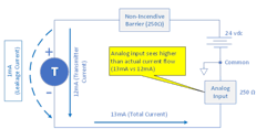
In Figure 3, there is moisture inside the transmitter housing resulting in 1 mA of leakage current across the “plus” and “minus” terminals of the transmitter.This produces a higher than actual current at the analog input (12 mA + 1 mA = 13 mA), so the HMI PV will show higher than the transmitter PV.
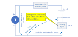
Another example would be for leakage from the negative signal wire to ground (Figure 4). In the example, 1 mA of leakage current (dashed line) flows from the transmitter directly to ground, bypassing the analog input. This results in the analog input seeing 1 mA less than the actual value—so the HMI would indicate proportionally below the actual value.
Interestingly, when performing high- and low-fault tests for SIS proof testing, we're actually verifying there are no dramatic leakage currents (among other potentially dangerous undetected failures). If there's a significant difference between the transmitter and controller input, either the high or low current fault test will fail because the fault indication won't appear when it should.
Greg: Can you give an example of a leakage current situation you've encountered?
Mike: I encountered a perfect example at one facility, where technicians had fallen into a pattern of routinely "recalibrating" a certain transmitter for what they described as "drift." They were blaming the equipment, but I know that brand, and it's not going to drift up and down like what they were seeing.
When they dug deeper, they discovered the actual culprit was moisture infiltration in a junction box caused by poor gland seals with a cable entering from the top. Once they corrected the moisture issue, the mysterious "calibration problems" went away.
Greg: How does moisture get into these supposedly sealed systems?
Mike: One question I often get is how moisture builds up in a J-box with downward-facing cable entries and shielding from rain. I saw this once offshore—the moisture got in via humidity in the air. Every night as temperatures cooled inside the J-box, pressure lowered slightly, causing it to "breathe in" moisture-laden air through tiny gaps in the seals. Overnight, the moisture condensed inside. The next day, as it heated up, a tiny amount of air would vent back out. This cycle repeated daily, slowly adding moisture until it became a problem.
Plants that rush through sealing cable glands often end up with moisture problems and subsequent leakage currents. It also happens during construction or installation, and nobody realizes until moisture builds up enough to become a problem, possibly years later.
Get your subscription to Control's tri-weekly newsletter.
Greg: What's your recommended approach for troubleshooting signal loops?
Mike: A methodical divide-and-conquer strategy works best. Here's a basic approach:
- Start at the source—use a HART communicator to drive the transmitter output to 100% (20mA).
- Verify both endpoints—simultaneously measure the transmitter output current with a calibrated process meter, and check what value appears at the controller’s analog input.
- Localize the problem—if readings match at 20 mA but show incorrect process values, check scaling parameters. If readings differ, the problem lies somewhere in the signal path.
- Isolate the fault—systematically measure current at accessible points (junction boxes, marshalling panels). Pay special attention to measuring both wires separately, as leakage current may affect them differently. Another option for isolating or confirming the fault is to disconnect the signal wires at the transmitter and at the analog input, and measure resistance between the wires at each point, as well as resistance to ground. The readings should show OL (very high ohms)—any readings below 100K to 1M ohms indicate a likely problem. In many cases, resistance checks are the best approach to find the specific location and path of a partial fault.
- Confirm and repair—address the root cause (typically moisture ingress, loose connections or ground faults), and implement preventive measures. Then reconnect and drive the transmitter to 100%, and ensure the human-machine interface (HMI) reading corresponds.
Greg: What about shield grounding on the signals?
Mike: Shield grounding remains one of the most misunderstood aspects of 4-20 mA loop installation. The purpose of a shield is to intercept electromagnetic interference before it reaches the signal conductors. For it to work, the shield must provide a low-impedance path to ground for these induced currents. The shield should be connected at one end only, or it will cause ground-loop problems. Typically, the signal shield is connected to the controller side of the signal path. We should never ground both ends of a 4-20 mA instrument’s signal shield wire.
Greg: Are people often confused by various grounding requirements?
Mike: Yes. I've seen situations where technicians assumed they shouldn't connect the transmitter housing ground because of confusion with the shield ground. The transmitter housing sometimes includes an external connector for installing ground wire, which is used for transient protection from lightning strikes, and is essential if the transmitter is going to use surge suppressors—it is not the signal shield.
Many transmitters require implementing transient protection for various installations, such as SIS requirements. If this ground isn't properly connected as specified, the transmitter can experience problems from nearby lightning strikes. I saw one facility that had replaced countless transmitters, until one savvy technician recognized the issue, and started replacing the bad grounding wires. Problem solved.
Greg: You mentioned that calibration checks should include HMI readings. Why is this important?
Mike: Since any leakage current in the 4-20 mA path causes an error between the transmitter and the controller/HMI, it's important to record the controller or HMI values during calibration checks to ensure the signal path is also error-free.
Studies by Automation Research Corp. and others show more failures and problems occur in the signal path than in the transmitters themselves nowadays, thanks to improvements in modern transmitters. So that classic "transmitter-only" calibration check that many people do is a wasted opportunity to catch looming problems if they aren’t verifying HMI values during those checks.
My own observations are that, for plants with non-ideal seal and gland maintenance practices, signal current leakages cause at least as many problems as actual transmitter failures or random drift. But many maintenance practices in the I&C realm are still based on traditions from the 1980s and 1990s.
Greg: What about the issue you mentioned regarding confusion between transmitter saturation and alarms?
Mike: It’s another cause of problems. If personnel understand that saturation is the range the 4-20 mA signal can drive to outside the standard 0-100% range (typically 3.9 to 20.5 mA depending on transmitter configuration), and that the fault value is outside those values to differentiate a fault from saturation, they can use these symptoms as a huge aid in troubleshooting efforts, and will also better understand procedures such as SIS proof tests and so forth.
Greg: What key points should engineers know more about with 4-20 mA loops?
Mike: Engineers should consider these points on 4-20 mA signals:
- Power budget calculations should be performed during design, not discovered as problems during commissioning. For each loop, calculate voltage drops across all components at maximum current (typically 21.75mA for alarm conditions);
- Wiring specifications should include clear requirements for shield termination, grounding, and separation from power cables;
- Clearly specify if inputs are isolated or non-isolated (i.e., a shared common);
- Loop diagrams should clearly show if the common lead is grounded and how. Loop power supply wiring diagrams should be available, so technicians can see the full circuit;
- Component selection requires attention to the entire signal path. A transmitter and control system that work perfectly in a loop by themselves may fail when barriers, indicators or other components are added to the loop; and
- Field verification procedures should specify measurements during FAT/SAT/commissioning, which record worst-case transmitter voltage (during high-fault current output) to confirm adequate voltage margins exist throughout the loop.
Greg: What should technicians focus on?
Mike: Technicians’ troubleshooting skills directly impact plant reliability. They should focus on these four areas:
- Systematic measurement and analysis based on actual understanding is more effective than intuition or past experience. Develop an understanding of fundamental principles, and use a logical approach based on drawings and reference information rather than guessing.
- Understanding normal values for voltage and current at each point in the loop allows technicians to quickly identify abnormalities. They should know what 'good' looks like before trying to fix 'bad’.
- Partial failures, like leakage currents through moisture, are often more difficult to diagnose than complete failures like open circuits or direct short circuits. They should learn to recognize the symptoms of these subtle problems.
- Documentation of findings, even for simple fixes, helps build a history that may reveal patterns and prevent future issues.
Greg: What has surprised you most about skills in the I&C craft?
Mike: One surprising thing that happens repeatedly is encountering situations where leadership assumes someone is highly skilled because they've been doing the job for decades and sound confident. Many times, they’re genuinely confident and simply don't realize what they don't know.
On several occasions, I assessed very senior technicians that everyone assumed were very solid, only to find they didn't understand some fundamentals. They had enough experience to usually get things running again, though sometimes with inappropriate fixes.
One of the most successful approaches I’ve found to determine someone’s skill levels, whether in instrumentation, automation or engineering, is to go through various procedures and ask, “Why did you do that step?" If they don't understand why they did a common procedure, there's a problem. Another similar approach is to watch them troubleshoot a real problem, and ask why they're taking each step and what their readings mean. It's incredible how much you can learn about someone's competence with that simple three-letter question.
Greg: These fundamentals are needed for process automation and safety systems. Better measurement and final control element accuracy and reliability translates to better process performance, less SIS activation and better SIS performance. My book, Process/Industrial Instruments and Controls Handbook, Sixth Edition (McGraw Hill, 2019), provides additional assistance via concise knowledge on calibration, installation, maintenance and best practices for nearly all types of instrumentation.
Top 10 good news and bad news
- The good news is that smart instrumentation was approved. The bad news is it’s a dumb application.
- The good news is the control valves aren’t oscillating. The bad news is the loops are all in manual.
- The good news is the new project manager is a process control engineer. The bad news is you are the project manager.
- The good news is that all the process variables are drawing a straight line. The bad news is they’re off scale.
- The good news is that digital positioners were added to all the control valves. The bad news is the actuator, coupling and linkage package is nicknamed “Sloppy Joe.”
- The good news is the loops are no longer oscillating automatically. The bad news is the plant is shut down due to the loops being in automatic.
- The good news is that your group’s name has “advanced” in it. The bad news is the full name is “advanced aged engineers.”
- The good news is you reached the level to work through “others.” The bad news is there are no “others.”
- The good news is you have a creative new office. The bad news is it has imaginary walls.
- The good news is that you’ve been offered a retirement package. The bad news is there’s a gift certificate to the plant cafeteria.
About the Author

Greg McMillan
Columnist
Greg McMillan retired as a senior fellow at Solutia Inc., now a subsidiary of Eastman Chemical, in 2002. He was an adjunct professor in Washington University Saint Louis’ Chemical Engineering Department 2002-04, and retired as a principal senior software developer at Emerson Automation Solutions in 2024.

Leaders relevant to this article: