Closing the SMART instrumentation knowledge gap

Key highlights
- The article explains how SMART transmitters are understood and maintained, especially the misapplication of legacy analog practices to modern digital instruments.
- It demonstrates how poor understanding of SMART calibration principles can lead to incorrect URV/LRV adjustments, misdiagnosis of errors and degraded system performance or safety margins.
In this second of a three-part series, Mike Glass, owner of Orion Technical Solutions, discusses common, critical knowledge gaps in instrumentation and controls. By identifying these gaps, organizations can better address training needs, and design improved systems, procedures, and maintenance programs to boost team performance.
Orion specializes in instrumentation and automation training and skills assessment. Glass spent nearly 40 years in the I&C field across multiple industries, including more than a decade assessing and developing automation specialists and instrument technicians for offshore oil and gas operations.
Mike, in our previous column, you discussed the common knowledge gaps in understanding 4-20 mA current loops. What other common gap areas have you observed in the I&C field?
Mike: Another problem area is with self-monitoring and reporting technology (SMART) instrumentation. Although SMART transmitters are common, technicians and engineers still treat them like their electronic analog predecessors, failing to factor technological advances and functional changes into their engineering designs or maintenance plans and procedures, and struggling to troubleshoot them effectively.
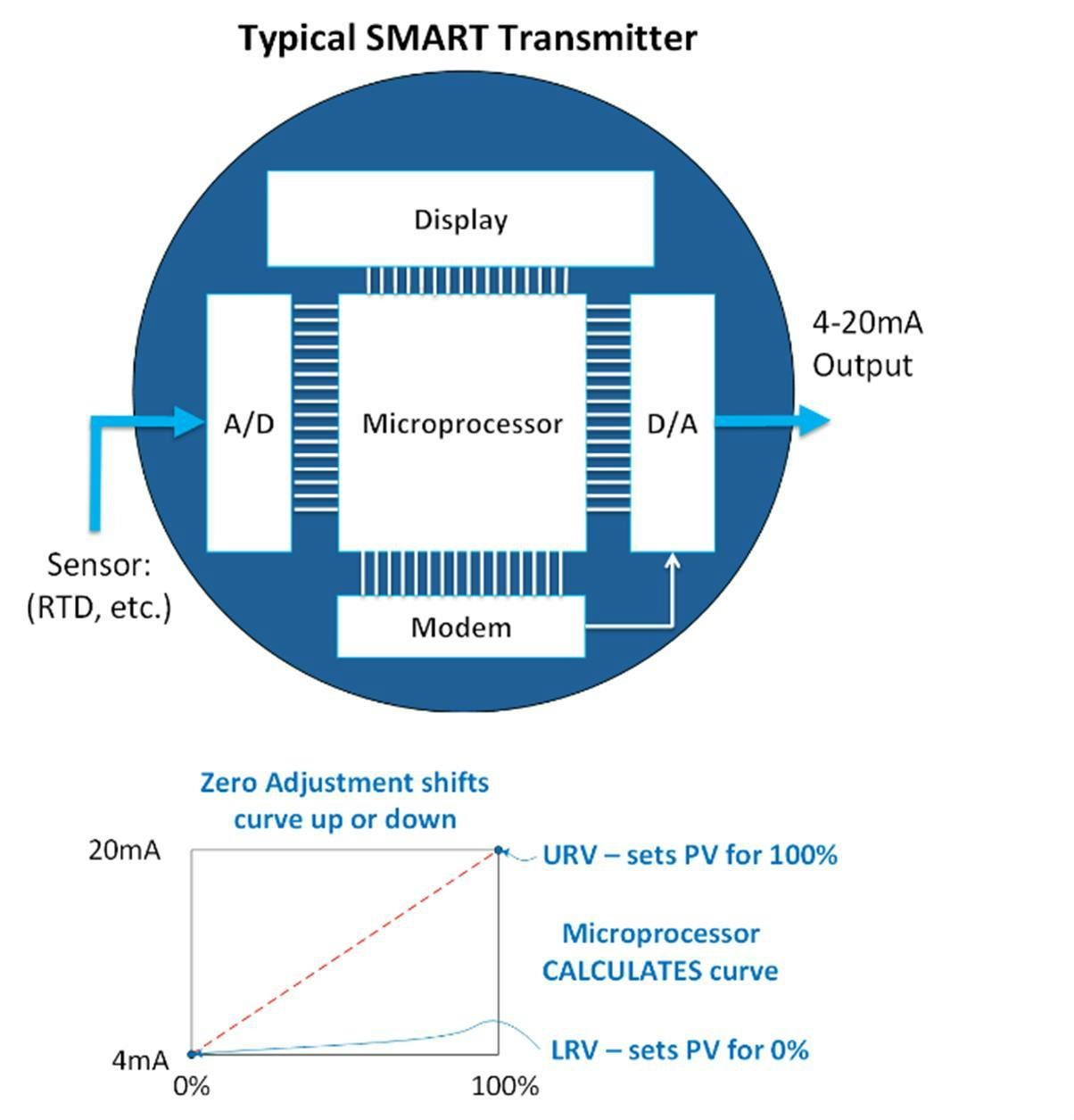
A typical SMART 4-20 mA transmitter is centered on a microprocessor and consists of five major functions as illustrated in the diagram below:

- The microprocessor does the scaling, linearization and compensation calculations, as well as various analyses, diagnostics and overall communications.
- The analog-to-digital (A/D) section converts the input signal to digital format for use by the microprocessor.
- The modem controls the modulation of the HART signal for digital communications.
- The digital-to-analog (D/A) section drives the 4-20 mA output as commanded by the microprocessor, which is based on the measured value compared to the upper-range value (URV) and lower-range value (LRV).
- Most systems have an integrated display that shows key information relevant to the transmitter, such as measured value (MV) or primary variable (PV), output percentage, calculated output mA, diagnostic alerts and other information depending on the model and configuration.
The transition to SMART instruments began in the 1980s, when microprocessor-based transmitters started to replace purely analog electronic transmitters. By the early 2000s, SMART transmitters became the industry standard, yet few organizations conducted appropriate engineering for the changes, resulting in minimalistic installations that failed to take advantage of many benefits or potential improvements.

Advances in SMART instrumentation have fundamentally altered the inner workings of the instruments, thereby affecting configuration, calibration, maintenance and troubleshooting.
Technology continues to advance at an accelerated pace. The next decade has the potential to be a productive and exciting time for the I&C world. Unless industry begins earnestly training and developing technical personnel on the field’s underlying principles, it may be fraught with challenges.
Greg: What fundamental differences between SMART and analog transmitters do people commonly misunderstand or misapply?
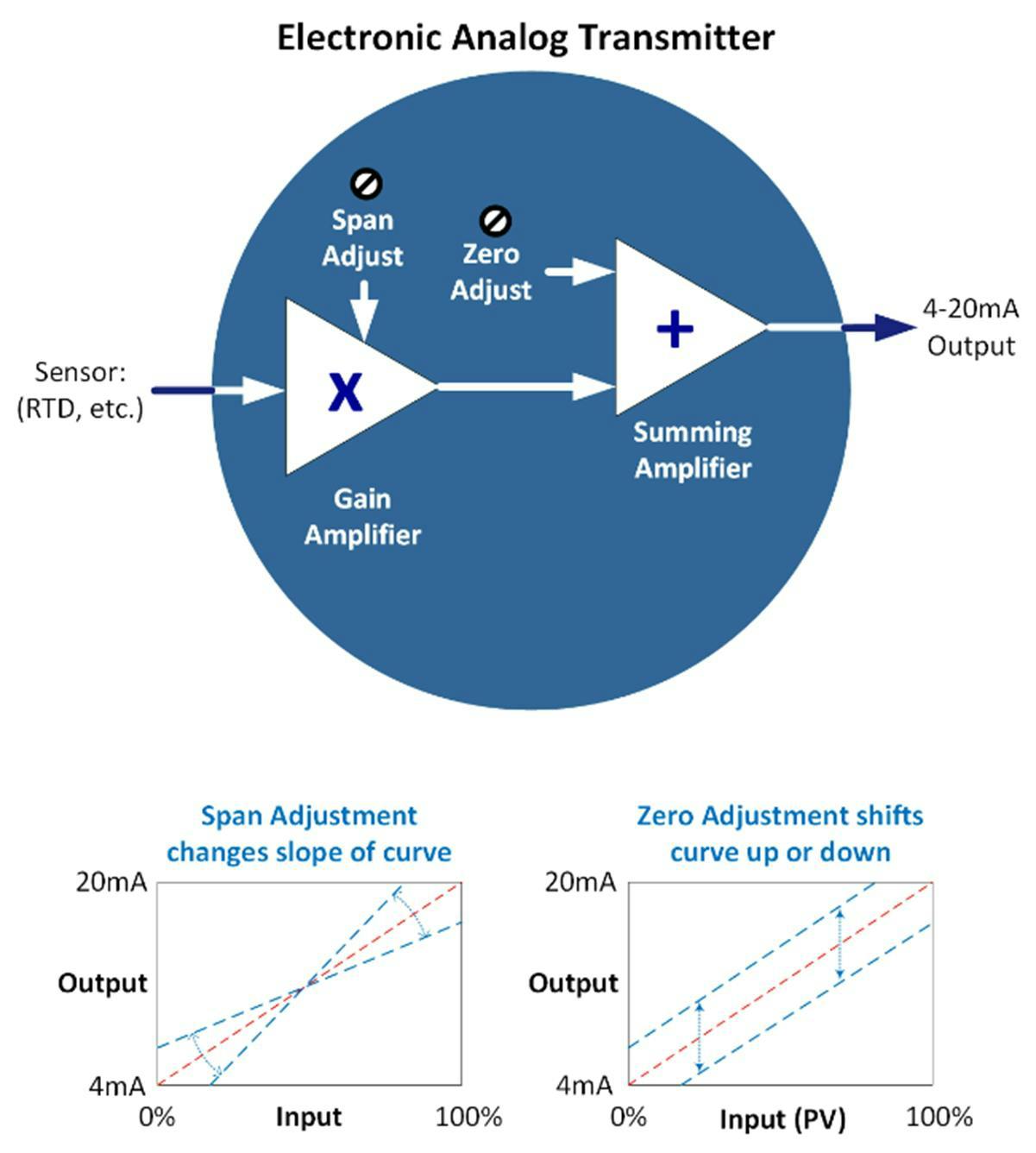
Mike: The most common oversight involves how measurements are processed, and how instruments are configured and calibrated. In short, older analog transmitters typically used electrical zero and span potentiometers that controlled electronic circuits to adjust the slope and offset of the output signal.
SMART transmitters perform the scaling (and other math) in the microprocessor, based on the LRV and URV entries.
Although SMART transmitters use microprocessors to perform the basic transfer function math of converting an input signal to an output signal, there are two key areas where calibration drift can still occur: the A/D section, where sensor input is converted to digital values, and the D/A section that creates the 4-20 mA output. When discussing SMART transmitters, I refer to these adjustments as "calibration trims,” and emphasize they’re fundamentally different from zero/span adjustments of the older analog transmitters. Understanding the difference is essential for proper maintenance and troubleshooting.
The overall transfer curve (relationship of input to output) is digitally calculated in SMART transmitters based on the URV and LRV. The processor also calculates for temperature compensation, detailed linearization and other math to a level of precision that would have been impossible with older analog circuitry. This is because, in older systems, each additional correction factor required additional analog circuits resulting in more cumulative analog errors. There was simply a point of diminishing returns on the calculation and compensation capabilities of analog instrumentation.
The advantage of using a microprocessor for calculations is its ability to perform very complex calculations with extreme precision. For example, with a 20-bit microprocessor, this precision is approximately one part in one million, far exceeding what was possible with analog circuitry. The ability to perform more detailed compensation and linearization calculations is one of the main reasons that SMART instrumentation has superior stability and accuracy compared to the old analog equipment.
Another reason newer SMART instrumentation is so much more accurate and stable than older equipment is because of the steady improvements in precision of solid-state electronics through the decades.
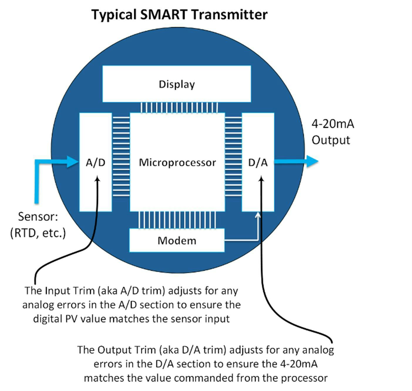
Since the basic range and scaling is established by the URV and LRV entries in the microprocessor, the calibration trims are only making minor adjustments of specific errors in either the A/D input block or the D/A output block.
Greg: What other skills gaps do you see in the differences in how SMART transmitters are calibrated compared to older analog transmitters?
Mike: The way calibration trims of SMART instruments are performed is different from the old-style, zero/span adjustments of analog instruments. In analog transmitters, users adjusted the zero-and-span potentiometers until they aligned the slope and offset of the curve into place. In effect, analog transmitters acted like a single transfer function that the technician had to adjust into place using iterative adjustments of the span and zero potentiometers.
However, when trimming the input or output blocks of SMART transmitters, users typically enter the applicable readings and target values into a HART communicator, and the transmitter internally calculates the adjustments required to mathematically correct the error, with minor user approval and confirmation buttons. This difference in how calibration adjustments are made causes considerable confusion for folks, who originally learned older electronic analog instrument calibrations, where users had to manipulate the curve into place.
The difference in the actual calibration steps is why so many untrained technicians make the mistake of fiddling with the URV and LRV to counter-correct for A/D or D/A calibration trim errors. Wrong as it may be, adjusting the URV and LRV parameters seems similar to the old-school, zero-and-span adjustments they learned on older, analog, pneumatic and electronic instruments, and it will have seemingly similar impacts on the output.
Greg: Do you have any examples of specific calibration problems like this that you’ve encountered?
Mike: One common mistake I’ve witnessed is where the local PV read 10, 510 and 1,010 PSIG for a simulated 0, 500 and 1,000 PSIG applied test pressure, causing a corresponding +1% output error.
Instead of properly trimming the A/D input section (the real source of the problem), the technician offset the URV and LRV to make the final 4-20 mA output look correct. The technician entered approximately 10 PSIG as LRV and 1,010 PSIG as the URV to accomplish a result that seemed right on the 4-20 mA output, based on the input conditions. However, two wrongs don't make a right, even in the I&C world. As you can guess, the next technician is likely to be confused, and add even more confusion and more errors to the mix when they properly correct the A/D trim error.
A similarly false approach is sometimes applied when the output section drifts, and tries to correct it by altering the URV and LRV values. The telltale sign for each of these bad practices is when you see URV and LRV values that use strangely offset numbers.
I always teach technicians to immediately verify URV and LRV anytime they connect to a transmitter. It’s been surprising how many times these URV/LRV offset mistakes are discovered—even on critical safety systems.
If technicians don't fully understand SMART transmitter operation, they often manipulate whichever section that they know how to adjust, and offset that section to produce the readings they want to see at a particular spot, without recognizing they’re adding new errors to the system that will cause other problems in the future. I’ve also seen this same mistake by poorly trained automation personnel, who offset scaling values in the DCS or PLC to counter-correct for various errors.
Greg: Are there any other common misconceptions you run across with SMART transmitters?
Mike: Another misconception that often happens is that personnel falsely assume that the digital mA reading on a SMART transmitter's LCD display (or via HART communications) is the measured current. Most I&C professionals realize that mA indication on the transmitter face (or as read via HART communications) is the expected 4-20 mA output based on the PV reading, but it’s easy to see how someone would draw that conclusion if they don’t understand the SMART transmitter. It would be great if all the instrument vendors would simply show that as calculated mA, instead of simply mA to help prevent the frequent misconceptions this causes.
Years ago, I ran into several technicians who weren’t bringing their process meters out to perform calibration checks. When I inquired how they were obtaining the mA readings, they said they wrote what they saw on the HART communicator. I discovered that both instrument shop leaders (each had more than 30 years in the field) were teaching junior technicians that the mA value on the HART communicator was measured current. Tribal knowledge can be a real monster in some situations, so you must verify that the supervisors and people providing the training and mentoring of new or junior personnel are adequately knowledgeable. Ironically, many of the biggest systemic skills gaps that I discovered over the years usually originated from senior (but misinformed and overconfident) technicians or engineers who weren’t properly trained.
While some of these mistakes and knowledge gaps sound extreme and unlikely to well-trained personnel, they’re quite common across most industries. It’s surprised me over the years, and it's a recurring theme—especially for sites with weak technical screening and minimalistic developmental programs. I’ve learned to never make assumptions about someone’s knowledge, skills or abilities until I thoroughly assess them.
When it comes to troubleshooting, misconceptions like these will lead technicians in circles and result in many needlessly swapped parts and other problems, as well as extended downtime or degraded safety margins. Or, they may simply record a passing calibration check when one or more parts of the transmitter were out of calibration tolerance.
Greg: What types of questions do you recommend for someone who wants to verify the knowledge level of their personnel to ensure they understand these issues adequately?
Mike: First, ask them to sketch a block diagram of the main components of a typical SMART transmitter, and explain what each block does and how each relates to typical maintenance tasks. If they can do that, they’re typically at least baseline competent.
Then, present scenarios like the following, and ask them to explain the solution:
- The simulated sensor input doesn't match the PV on the HART communicator. The answer of course, is to do a calibration trim on the A/D input section.
- The mA reading on the transmitter display shows 16.15 mA but the actual output current on a process meter reads 15.99 mA. Other checkpoints show similar mismatches. They should recognize that the 16.15 mA reading on the transmitter display is the expected output, and the 15.99 mA is the actual measurement. They should also recognize the need for a calibration trim of the D/A output section.
- The transmitter is outputting 12.00 mA, but the HMI shows 51.3%. In this case, they should recognize that, if the transmitter output doesn't match the HMI, the error is between the transmitter and the HMI (not in the transmitter). This indicates either leakage current in the loop (due to water in a conduit or j-box, for example), or a potential issue with the PLC or DCS input card calibration, configuration or input scaling.
- Try to directly observe the individual performing an actual calibration check of a typical SMART transmitter, ideally on an instrument that’s likely to have some drift error, or a device that you’ve intentionally added an error to. Observe every detail, including their handling of forms, radio comms, error pass/fail calculations, and ask them how they'd go about correcting possible problems or errors. This can also be done on a bench with a spare transmitter, or even just as a discussion, using their sketch of the system if necessary. As they go over the procedure, ask them to explain the reason for each step, and ask contingency or what-if questions, such as, what if the 50% output is 12.10 mA instead of 12.00? Per our discussion in the last column on the 4-20 mA weaknesses, always ask the why questions for each step.
Get your subscription to Control's tri-weekly newsletter.
With some simple questions and practical task observations, it typically becomes very evident who needs some up-skilling.
In my opinion, any plant that doesn't periodically have a high-level, properly credentialed SME observe I&C personnel perform specific maintenance tasks like calibrations and SIS-proof testing is making some dangerous assumptions. Assuming everyone is competent based on their years of experience or the degree they once held is a dangerous game. Many can talk the talk, and may even sound knowledgeable or confident if you don’t dig very deep, but when you start doing detailed assessments of I&C personnel, you’ll likely be surprised and possibly shocked, and pretty concerned in many cases.
From what I’ve observed, about 10-25% of technicians and a large number of I&C engineers at most sites have significant gaps in this area.
Greg: Many of the same competency-related issues with SMART instruments have gained market dominance. In 2019, we updated the 6th edition of the Process/Industrial Instruments and Controls Handbook (McGraw-Hill) to include detailed coverage of topics such as you’re discussing.
Mike: That's a great book! It is sitting right here beside my desk and I often use it. I believe each shop should have reference copies of books like it, with lots of highlighting and sticky notes in them. One good mentor steering developing technicians to steadily read and use references can do amazing things in a shop with technicians who are willing to do the work needed to learn and grow. Unfortunately, I find that very few instrument shops have helpful references on hand, even though it is one of the easiest and most cost-effective, supplemental ways to upskill a team on the countless niche areas we run across in the field.
Greg: Why do you think these misconceptions about SMART transmitters persist despite decades of use?
Mike: As we discussed in our previous column, the erosion of industry training programs and degradation of employment screening quality continues to cause problems in the I&C field. With SMART transmitters, the problem is compounded because these devices require both traditional instrumentation knowledge and an understanding of the newer SMART technology.
All too often, technicians are simply shown how to follow specific steps for SMART transmitters without understanding the underlying digital principles that make them fundamentally different from analog devices. Technicians end up with procedure-based knowledge, rather than conceptual understanding, which fails when they encounter situations outside their memorized routines, including troubleshooting and recognizing flaws in procedures.
What's particularly concerning about SMART instrumentation is that the knowledge gap is widening as instrumentation becomes increasingly complex and feature-rich.
Greg: Do you also see weaknesses in the understanding and implementation of diagnostic capabilities of SMART instrumentation?
Mike: Yes. It’s another major weakness across most industries. Most sites use only a small fraction of the potential benefit of SMART transmitters, and even less of the diagnostic capabilities of modern SMART valve positioners. The knowledge about diagnostic capabilities of all instrumentation is usually weak at best—for engineers as well as technicians.
SMART instruments can detect numerous conditions that would’ve been impossible with old analog technology—such as plugged impulse lines, electronics failures, sensor drift, power supply issues and configuration problems. However, organizations rarely take advantage of these powerful diagnostic capabilities, even though they're already available in instruments that have been in their plants for many years or decades.
Many plants simply replaced old analog devices with SMART instruments once the old devices became obsolete and they could no longer purchase them. However, many sites are still running their instrument calibration and maintenance programs for those new SMART instruments just as they did for devices from the 1980s.
The diagnostic capabilities already available for existing instrumentation at most plants could (and should) be a bigger game changer for overall performance and reliability than most highly touted new trends, slogans and maintenance improvement programs. Most of those capabilities just sit there, completely unused, because so few plant personnel understand their possibilities. The illustration below is just a sample of some of the incredible diagnostic and analytical capabilities of today’s SMART instrumentation:

Greg: What are your observations on I&C personnel's knowledge of communication capabilities in SMART instruments?
Mike: While most technicians can use HART protocol in standard situations, many don’t understand how it works and can’t troubleshoot communication issues. This knowledge gap also extends to newer technologies like Wireless HART and Bluetooth interfaces, which are transforming how we can interact with field instruments. Most personnel need to learn much more about these technologies before they can properly use them.
These wireless options offer compelling advantages for many situations. Consider a SMART valve positioner that’s not connected to a HART network. With a simple Bluetooth HART modem installed (available with many instruments today), technicians could go out with a simple personal digital assistant (PDA) or other handheld device, and easily check for diagnostics without needing to open or make physical connections to the positioner. If any alerts or warnings due to stiction, position sensor problems, diaphragm leaks, spring problems, air supply problems, I/P errors or other issues are present, they’ll be seen, and can be corrected before the problems worsen. Powerful diagnostics like this can drastically improve predictive maintenance performance on some of the most common (and avoidable) causes of plant downtime.
Greg: What recommendations would you give to engineering teams designing systems with SMART instrumentation?
Mike: Engineers should ensure they don't fall into the assumption trap of treating newer replacements like older or obsolete equipment. They must consider the full capabilities, limits and specifications of SMART transmitters during design, including:
- Get applicable training to fully understand SMART instrument technology and applicable emerging comms options, and thoroughly review applicable reference manuals for specific plant devices to ensure proper implementation.
- If permanently installed diagnostics monitoring (or displays) aren’t available, plan how technicians can quickly and easily connect to check for diagnostic alerts or warnings without needing to open the instrument housing (by installing Bluetooth connectivity modules, for example).
- Develop maintenance procedures that leverage the predictive maintenance power of SMART instrument diagnostics.
- Document all applicable configuration parameters in specification/configuration sheets—not just calibration range or the URV/LRV.
Greg: What advice would you give to technicians working with these devices?
Mike: For technicians, I suggest:
- If possible, get formal practical training on SMART technology and related topics.
- Once you understand SMART technology in general, crack the books. Learn how each device and technology actually work with your specific devices.
- Go beyond the procedures or steps of common tasks. Learn and fully understand the how and why of each step of each procedure.
- Become familiar with the features and capabilities of your specific SMART instrumentation.
Greg: What are the key takeaways you'd like readers to remember about SMART transmitter technology?
Mike: SMART instruments aren't more accurate versions of their analog predecessors. They use fundamentally different technological approaches, and therefore need a rethink of procedures and entire maintenance strategies and procedures. They offer many powerful, new features and capabilities that are likely underutilized. If personnel don’t understand how SMART instruments work, organizations will miss opportunities for improved reliability and efficiency, and will suffer increased downtime, slower troubleshooting, more expenses and reduced safety margins.
We want to hear from you - what do you think about the current state of training in the automation industry?
Top 10 dumb instrumentation installations
- Long and uninsulated impulse lines
- Unknown fluids in equalization lines
- Long capillary lines
- Thermal mass flow meters on fluids with changing compositions
- Thermowells with insufficient insertion length
- Temperature and pH sensors not considering cross-sectional profile in pipelines
- Temperature sensors not touching thermowell tip due to lack of spring loading
- pH sensors with solid reference junctions not reaching equilibrium in batch operation
- pH sensors with wrong glass and reference junction for temperature and composition
- Readback to smart positioner a lie due to slop in linkages and shaft windup
About the Author

Greg McMillan
Columnist
Greg McMillan retired as a senior fellow at Solutia Inc., now a subsidiary of Eastman Chemical, in 2002. He was an adjunct professor in Washington University Saint Louis’ Chemical Engineering Department 2002-04, and retired as a principal senior software developer at Emerson Automation Solutions in 2024.

Leaders relevant to this article: