Best practices for override control

This Control Talk column appeared in the January 2020 print edition of Control. To read more Control Talk columns click here or read the Control Talk blog here.
Greg: Override control is the principal means of doing PID constraint control to optimize process operation and prevent abnormal operating conditions. It’s a challenge to make sure the transition between the PID controllers for each constraint is smooth and effective, and the operator can make adjustments, change modes and understand what is going on. Each PID is tuned for its process dynamics and desired performance. Each PID output goes to a signal selector. Whether a high or low signal selector is used depends upon which direction is most beneficial for process performance and safety. The fact that each PID is trying to do its own thing and integral action is never satisfied, always trying to drive the output, makes it a challenging application. There may be a valve position constraint (e.g., coolant valve opening for reactor temperature control or user valve opening for compressor pressure control), in which case the PID controlled variable is the maximum or minimum throttle position still offering good process control as discussed in the Control Talk column, “The best valve position control.” The many undiscussed necessities for override control are offered here in a conversation with Peter Morgan, leader of the ISA 5.9 Standards and Practices (S&P) working group for PID algorithms, who has considerable practical experience with override control.
Peter, what is the concept and an example of override control?
Peter: An override control strategy employs two or more controllers in a configuration that allows one controller to act to maintain or regulate one process variable (the main controller) while another controller monitors a different process variable (the constraint variable) to intervene through a high or low signal selector if the constraint is exceeded. Output tracking and integral tracking modes are used to make the transition effective and bumpless. In output tracking, the PID output follows a track value. The integral (I) term continuously initializes to the difference between the track valve and the sum of the proportional (P) and derivative (D) terms. In integral tracking, the PID integral term follows the track value. Controller output is the track value plus the P and D terms. Unless the control error is zero, the PID output is the track value with an error dependent on offset applied.
While the strategy is a simple one in principle, without adding or configuring features that prevent integral wind-up and avoid latency in override action, the strategy will not perform well. Also necessary are provisions to ensure that transfer of the main loop to manual by the operator occurs without disturbance. This is not typically a concern with a single controller acting directly to position the final element, but is an issue in override control. If a vendor does not provide “integral tracking” as an accessible mode, selecting output tracking and a track value that is offset by gain times control error is sufficient to achieve the required functionality when integral tracking is required.
Consider the case where hot water is supplied to a header and the flow regulated by a PID controller by adjusting a valve. Piping design limits require that the mixed stream temperature be limited by override acting on the valve if the critical temperature is exceeded.
The logic is implemented using two PID control algorithms acting through a low signal selector to position the valve. Because the PID function block and HMI faceplate includes an Auto/Man station (a common feature of contemporary programmable systems), so that there is only one point for manual intervention, the override (temperature) controller is locked in Auto. Depending on the implementation platform, this may be a configurable feature of the PID block, but if not available, the mode may be forced to Auto from another block through the setting of a mode flag. The importance of locking the override controller cannot be understated, since this avoids possible operator error in an emergent situation, when the operator might otherwise attempt to adjust the valve via the override controller.
Since there is the possibility that the operator would need to transfer the flow controller to manual when the temperature override is active, the logic includes provisions to initialize the flow controller so that its output matches the output of the low signal selector (same as the temperature controller output in this instance). For this purpose, when the flow controller is transferred to manual, the flow controller is transferred to output tracking for one execution cycle so that the output aligns with the track value. After one cycle, the flow controller returns to normal manual with no disturbance in output. Since loop transfer from auto to manual is not normally a concern, this requirement can be easily overlooked, and is an example of the need for the control specialist to consider the behavior of the controls in every possible operating mode and transfer between modes.
When the control error is negative for both the flow controller and temperature controller, the mode of the controllers will alternate between normal and integral track modes every execution cycle. Since each controller is aligning with the other with a negative offset, every execution cycle, there is an accumulation that (without the filter applied to the track value) would result in rapid uncontrolled closure of the valve, especially when the execution interval is very short. In practice, the first-order filter time constant should be set to match the shortest controller integral action time setting.
Note that in this example, there is only one override controller, but there is no limit to the number of override controllers in a strategy provided that the tracking modes are coordinated. For instance, pump speed might be modulated by a flow controller, with override controllers acting on pump discharge pressure and pump suction pressure so that preemptive action might be taken to avoid the tripping of the pump.
Figure 1 shows an override strategy with provisions for bumpless transfer to manual shaded for clarity.
Greg: What might users see for this example?
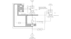
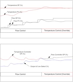
Peter: Initially, the temperature is normal (below setpoint) and the temperature controller output is following the output of the low select (flow controller output at this time), with a positive offset that is proportional to the control error. Until the temperature reaches the constraint value (temperature setpoint), the valve is positioned by the flow controller. As temperature rises, the offset reduces until it becomes negative when the temperature exceeds the setpoint and the output of the temperature controller (still in integral track mode) becomes less than the flow controller output. At this point (actually the next execution cycle), the temperature controller exits the integral track mode and modulates the valve while the flow controller enters, and stays in, the integral track mode until the flow controller error is negative.
Figure 2 illustrates the behavior of the controls. Note that the responses are not from real time data and are illustrative only.
When an override is active, the condition should be indicated on the process graphic. This can be based on the signal selector status, but is commonly based on presenting the controller track status on the HMI graphic. Whether or not override action is alarmed is usually an operational decision based on the potential impact on plant production or related plant equipment.
Greg: Are there any other issues with respect to implementation?
Peter: Execution on a programmable system (e.g., DCS or PLC) is necessarily sequential. This can be both a blessing and a curse, especially if not accounted for in the implementation of a control strategy. In this case, all control logic should be in the flow controller control module/container and block execution defined so that Boolean states and analog values associated with tracking are calculated before the PID block is executed. Not following this practice can lead to improper initialization due to the use of states or Boolean values from a previous execution cycle.
Greg: I implemented an override control system decades ago that optimized batch reactor operation where production had been pushed to twice the design capacity because product became so profitable. The override control system reduced batch cycle time by 40% and eliminated reactor trips that had occurred nearly every batch because the coolant and vent system was pushed way beyond original design limits. There were 12 override PID controllers to address all the possible constraints. I opted to use proportional plus derivative controllers because of the exothermic batch reaction and the desire to avoid the complexities and undesirable actions of the integral mode. The operator could see which controller was governing the maximization of reactant feed rate, and the time each controller was selected was historized. It was found that four PD constraint controllers were active at various times in the batch. Better control by these controllers made the violations of other constraints unlikely.
For PID override controllers, I found that a signal filter needed to be applied to the integral track signal to prevent the unselected PID output from walking off to an output limit in the DCS I was using in the 1980s and early 1990s. The optimum filter time constant turned out to be the reset time setting. In the next-generation DCS I have used since then, a positive feedback implementation of integral action uses a filter with its time constant that is the reset time. When external-reset feedback (e.g., dynamic reset limit) is simply turned on and the signal selector output is used for external-reset feedback, integral action doesn’t interfere with override control, enabling the point of takeover being determined by error and gain setting in a positional algorithm for each PID. Shinskey and Harold Wade noted the ability of external-reset feedback to intelligently suspend integral in override control in the Control articles “The power of external-reset feedback”, “Under the hood of override control” and “Under the hood of override control: Part 2”. For a glimpse of the other possible opportunities offered by external-reset feedback, see items three through 10 in the Control Talk Blog “Missed Opportunities in Process Control - Part 3” and the Control feature article “How to specify valves and positioners that don’t compromise control.”
We assume a positional algorithm is being used. A velocity algorithm would cause incremental changes that are not necessarily in the best direction for constraint control unless special logic is implemented. The PID setpoint and tuning for constraint control is best done based on the position of the process variable in the direction of violation of the constraint represented by the setpoint.
Peter, what do you think of negative views expressed for “forced Initialization?”
Peter: When integral tracking and output tracking are properly used with a little (trivial) logic, there is no bump in the position demand for the final element and none during transfer to manual. The ability to force initialization and have it occur in one scan is a must. Bringing to mind several multi-valve, split-range valve loading strategies I’ve developed in the past, I know they couldn’t be made to work without forced initialization. Incidentally, I have used output tracking (forced Initialization) as a method of action augmentation, when, as long as the PV exceeds an upper limit, the controller output is ramped down. When the PV returns to the normal control range, the controller reverts to normal action without any discontinuity in the position demand (no bump).
(10) Sleep like a baby before a startup (less the midnight crying)?
(9) Get back early from startups?
(8) Have vendors ask what you think works best?
(7) Become the “go -to person?”
(6) Have your CEO smile at you?
(5) Inspire your children to become automation engineers?
(4) Get a knowing twinkle in your eyes like that wrinkled old technologist about to retire?
(3) Get asked what is your key to success?
(2) Get asked by operators to special meals in the control room kitchen?
(1) Become famous and a regular guest on late-night TV?
While I can’t guarantee this, reading 101 Tips for a Successful Automation Career and joining the ISA Mentor Program just might be the key to a much more rewarding future in automation.

About the Author

Greg McMillan
Columnist
Greg McMillan retired as a senior fellow at Solutia Inc., now a subsidiary of Eastman Chemical, in 2002. He was an adjunct professor in Washington University Saint Louis’ Chemical Engineering Department 2002-04, and retired as a principal senior software developer at Emerson Automation Solutions in 2024.
