Ensuring the right controller is in charge

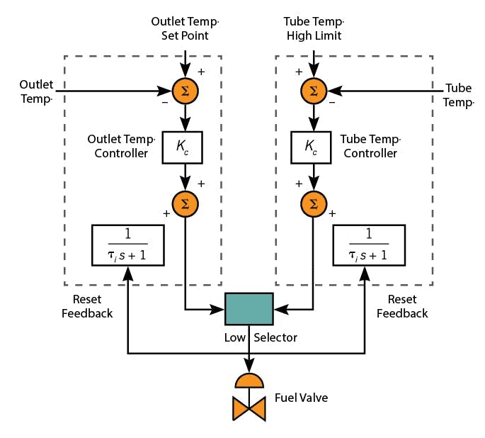
The diagram (Figure 1) from the article “Under the hood of override control” by Harold L. Wade, depicts a fired furnace heating a process fluid. The primary controller is the process fluid temperature controller (TC) in the lower right. If the process fluid is not hot enough, then the controller sends a signal to open the fail-close (air-to-open) flow control valve (FCV).
However, the temperature of the internals in the heater are of possible concern. The TC in the upper right monitors tube temperature. If it is too high, the override controller sends a low signal to the valve to reduce the tube T. The select block “<” executes a less-than test, selects the lower of the two signals, and sends the lower to the FCV.
Let’s use some numbers to explain controller interaction. To follow this story, you might place the T and manipulated variable (MV) values on Figure 1. The process T setpoint (SP) is at the setpoint of 430 oF. The primary controller output, MV, is 55%.
At this firing rate, the tube T is 550 ºF, which is below the 600 ºF safety limit. Therefore, the override/safety/secondary controller thinks the temperature is below the setpoint and more fire is required, so it integrates up to an output of 100%. Since 55% is less than 100%, the select block chooses 55% and tells the valve to be 55% open, where the process temperature is just right. Everyone is happy, but the secondary controller thinks, “Nobody ever listens to me.”
Over time, the process tube begins to get fouling (soot, scale, char), the inflow feed T drops, or process flow rate increases. As a consequence, the process T drops. The process T controller fixes the process T by increasing its output to 60%. However, the higher firing rate raises the temperature of tube T to 599 ºF, barely below the safety limit of 600 ºF, so the safety controller asks for more heat and remains wound up at 100%. The select block selects the lower of the two signals and sends 60% to the valve. Tube T is below the safety limit, and the process T is at setpoint. Meanwhile, the secondary controller is left “unhappy.”
As the disturbance continues, the primary controller must increase its output to 61%. It’s still selected, because 61% is less than 100%, and at 61% the process T is held at the 430 ºF setpoint, but tube T rises to 605 ºF. So, the safety controller drops its output to 99%. Since 61% < 99%, the select block still sends 61% to the FCV.
As time continues, the primary controller progressively raises its output to 63% then 65% to keep process T at its setpoint. The action raises tube T to 610 ºF then 615 ºF, which accelerates the safety controller integral reduction to where its output drops from 99% to 95% to 80% to 70%. Still, the select block chooses the primary output of 65%. Meanwhile, not everyone is happy as tube T is above the safety limit.
As time continues, the safety controller output drops to 65%, tied with the primary controller output, and the secondary controller drops to 64% before the FCV is told to close a bit. Finally, the safety controller is in charge, but tube T has risen to 618 ºF. The override controller progressively lowers the FCV to 54%, returning the tube T to—and keeping it at—the limit T. The action keeps process T as near to the setpoint as possible, but not enough to overheat the tubes. However, for a time, tube T was above the safety limit. How far above the limit and for how long depends on controller tuning and process gains, but it is not something you want.
Now with too low a firing rate to sustain process T, the process fluid exits at 417 ºF, below the setpoint, and the primary controller winds up to 100%. If the fouling, inlet T, or process flow rate issue is resolved, then process T will rise to 452 ºF, which is above the setpoint, and the primary controller integral will keep the output excessively high until it winds down to a value below the 57% signal from the secondary, when it is selected and returns to being in control.
Whichever controller is selected (in charge), the other (which is not in charge) will wind up. This causes a delay in the should-take-over-point and a persistance of the undesired outcome.
These type of control applications are variously termed override, safety, select, or switch control strategies. he override controller is variously termed safety, secondary or auxiliary.
Alternate override strategies
- Figure 1 has two controllers on the process. An alternate strategy requires one controller, the process temperature controller in the lower right. When tube T violates a limit place the primary controller in MAN and override the signal to the valve with a lower signal to the valve. But what signal value? If too large, then tube T remains excessive. If too small then tube T is well below the safety limit, but process T remains much lower than it could.
- It is advisable that process T to remain as close to the setpoint as possible. Therefore, keep the two controllers as shown in Figure 1, and select which controller sends its signal to the valve. If tube T is below the limit, place the auxiliary controller in MAN and use the primary controller in AUTO. When tube T exceeds the limit, place the primary controller in MAN and the auxiliary controller in AUTO. If the controllers are properly iniitalized in MAN, there will not be a bump in transfer. However, the auxillary controller will keep tube T at the limit, minimizing the deviation of te process T from its setpoint. Then when tube T falls below the limit, reverse the controller modes. An undesirable aspect is chatter in mode switching when tube T is near the limit and noisy. One could place a deadband on the switch point to eliminate the chatter.
- You can tune the controllers for very rapid wind down. Use a small integral time. Compensate with a small proportional gain, but this may undo desirable controller tuning for regulatory or servo action.
- You can tune the controllers with a large proportional gain so that when the error sign changes, the P action dominates the integral. However, this may undo desirable controller tuning for regulatory or servo action.
- One PID product to be aware of aware of has an option that when the integral reverses after hitting a limit, it makes it 16 times faster. I have no experience with this, but it seems like a reasonable fix, even though the 16 times is arbritrary.
- You can enter a lower than needed safety setpoint so the excess due to delayed switch-over to the secondary PV might still be within the safety limit. However, then the override will cause an extra deviation from the process, and the return of control to the primary still has the undesirable switch-over time and excess.
- You can change the wind up limit of each controller. In the example, the transfer should have happened at 63%, so the safety controller integral should be limited to 63%. However, how can one know that value and change it as appropriate to continually changing conditions?
- The reset feedback solution described here is to use a filter rather than an integral to determine the controller bias, and to use feedback to reset the bias.
Reset feedback method
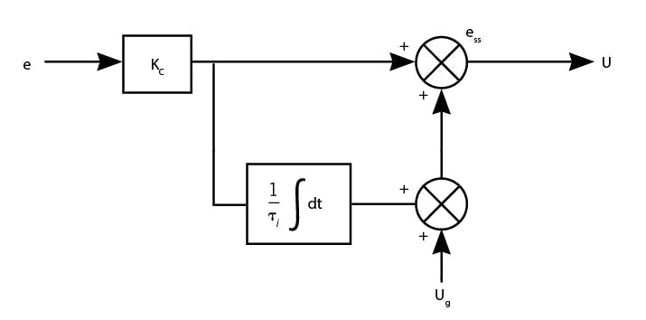
Start with Figure 2, PI control with calculus representation in the block diagram.
The diagram indicates to get the output of the controller, add to the proportional term (calculated as P = Kc ∙ e) to the adjustable bias value (calculated as B = U0 + Kc / τi ∫ e∙dt ).” Laplace notation for the diagram indicates the same:
û = Kc (1+1/(τis)) ê = Kcê + Kc/(τis)ê = P̂ + B̂
Mathematically, the equation is the same as:
û = Kcê + 1 / (τis + 1)û = P̂ + B̂
The second equation indicates to get the output of the controller, add to the proportional term (P̂ = Kc∙ ê) to the adjustable bias value (B̂ = 1/(τis + 1) û), which is calculated by a first-order filter of the controller output. It also means there was no need for Laplace notation.
Numerical code for this procedure can be done as:
e = SP – PV ‘actuating error
P = Kc∙ e ‘proportional term
B = (∆t/τi)MV + (1-∆t/τi)B ‘adjustable bias is the filtered MV
MV = P + B ‘add P to bias
In MAN mode the adjustable bias, B, is initialized with the current output (B = MV), and SP is initialized with the current PV value (SP = PV).
The Laplace notation-transformed second equation or the implementable third equation set is called internal reset feedback. It feeds back the controller output (the internal value) to reset the controller bias, B.
If the controller is in charge, then the method represented by either equation to calculate the controller output is exactly the same as PI control with the integral (within numerical approximation). However, if the controller is not in charge, then it still winds up to the 0% or 100% limit.
To limit wind up of the adjustable bias to the right value for the situation, the method is to use external reset feedback, (erf). The right value is the selected output, the value actually implemented. Use the selected output as the reset feedback signal to adjust the bias, instead of using the controller’s own internal value.
Numerically this would be done as:
e = SP – PV ‘actuating error
P = Kc∙ e ‘proportional term
B = (∆t/τi)MV + (1-∆t/τi)B ‘adjustable bias is the filtered MV
MV = P + B ‘add P to bias
Returning to the first illustration, just prior to the point where tube T controller should take over, the selected output is process T controller’s output of 62%. Using erf to determine the controller bias, the erf signal to the override controller has lagged to the selected 62%, which means that its bias is at 62%. The safety controller proportional term is its gain times the temperature deviation, which might be +1%. So, its output is 63%. The instant tube T exceeds 600 ºF, when the actuating error becomes -1%, override P action will reduce its output to 61% and at that instant, the select block will choose the safety controller.
The benefits are:
- There is no delay in time to let an integral wind down;
- There is no period of safety violation; and
- Regardless of the application or current context, the switch is at the right point, so the human does not have to specify that point.
The erf versions of PI control tune just like standard PI controllers. The reset feedback filter is equivalent to integrating the actuating error.
The equations are more complicated when derivative mode is included in the PID controller, and different with the parallel and series options. The manufacturer has several choices to mathematically model and then to digitally handle the extra feature. Any erf version of a controller should be the same as its PID original to a user. As a user, you just choose the erf option and specify what is to be used as the erf signal.
The select block might be greater than, depending on the process gain and whether a valve is ATO or ATC.
To tune either controller, that controller must be in charge. When tuning, bypass the select block so that the output of the controller you are tuning goes directly to the process.
Override applications
Override application categories include:
Health, safety, & loss prevention
- LEL, UEL, Dust in air
- Excess O2 in flue gas
- Toxic vapors in air
- Cavitation or flashing in pumps, valves and orifices
- Pressure or vacuum in columns and tanks
- High temperature (structural integrity)
- Low temperature (embrittlement of rubbers and gaskets)
- Level in tanks (overflow)
Product/process quality
- High temperature (char, degrade, melt, diffuse)
• Low temperature
(crystallize, phase separation, condense)
Equipment operation
• Choked valves, pipes, orifice
• Weeping, flooding, dry packing on trays
• Level in tanks (whirlpool gas in exit)
About the Author

R. Russell Rhinehart
Columnist
Russ Rhinehart started his career in the process industry. After 13 years and rising to engineering supervision, he transitioned to a 31-year academic career. Now “retired," he returns to coaching professionals through books, articles, short courses, and postings to his website at www.r3eda.com.
