By F.G. Shinskey
In almost every temperature and composition loop, the process we try to control has its dynamics distributed across space and distance from inlet to outlet. Attempting to lump its dynamics into dead time, plus lag, misrepresents its response and ignores information that can be useful in diagnosing behavior and estimating optimum controller settings. This is especially the case in heat transfer—common to all industries—where heat capacity and resistance are distributed across the entire process, and where the resulting dynamic properties are also subject to variation with flow. Temperature control, therefore, has its own behavior, requiring special attention for those auxiliaries that must provide heating and cooling over the full range of production rates.
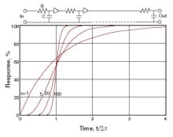
To introduce the identification of distributed dynamics, let’s begin with a series of equal first-order lags, observing how they may interact with one another. A distillation column is a perfect example of a multiple-lag process, illustrating both interacting and noninteracting lags. Figure 1 below shows the flow of liquid reflux into tray 1 cascading downward from tray to tray, eventually leaving tray, n, counter to the flow of vapor upward. Feed, condenser and reboiler are omitted to simplify the presentation.
FIGURE 1Noninteracting Lags
An increase in reflux flow entering tray 1 must raise the level above its overflow weir before outflow can begin to increase—a characteristic of a first-order lag. The same process is repeated from tray to tray, with the flow leaving tray n having the response of all the first-order lags in series.
Step responses of equal noninteracting lags.
Figure 2 describes the response of flow leaving tray n for n = 1, 5, 20 and 100, following a step increase in reflux. Time, t, is normalized by dividing by Στ, which in this case is simply the sum of all the lags: Στ = nτ, with τ being the hydraulic time constant of an individual tray, typically on the order of 5 seconds. Observe that the curve for n = 1 crosses t/Στ = 1 at 63.2%, a familiar property for a first-order lag. As n increases, the crossover point moves downward toward 50%, and the curves approach the response of pure dead time.
These are noninteracting lags. The flow entering a tray from above is unaffected by any level or flow on a lower tray. The flow of information is in the same direction as the liquid flow. The response is that expected from a series of equal lags uncoupled from one another, simulated electrically by a ladder network of equal resistors, R, and capacitors, C, isolated from one another by buffering amplifiers as shown in Figure 2; each individual time constant is τ = RC. The apparent dead time in this series of hydraulic lags will prevent us from controlling base level by manipulating reflux flow if there are more than a handful of trays. But surprisingly, the same trays behave as interacting lags when their composition response is examined.
Interacting Lags
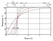
Consider the response of the analyzer in the overhead vapor line of Figure 1 to a change in reflux flow. Increasing reflux will reduce the amount of heavy impurity in the overhead vapor in a matter of seconds. But the effect does not stop there. The same increase in reflux flow affects both the composition and flow of liquid entering tray 2, which, in turn, affect the composition of the vapor leaving it and entering tray 1. This produces a secondary effect on the composition of the vapor reaching the analyzer from tray 1. The compositions of both liquid and vapor leaving the trays continue to change all down the column and back upward for a long time after new flow rates have been established. The response can be simulated by the electrical ladder network of Figure 3, where isolating amplifiers are not included. The series of interacting lags differs from a series of noninteracting lags in two distinctive ways: the total time response Στ increases much faster with n, while the shape of the response curve hardly changes at all!
The total time response can be estimated from the understanding that the first capacitor, C, in the ladder is charged through a single resistor, R, while the last is charged through the entire series of n resistors. The total time response then varies with the sum of the series of integers 1 through n:
The sum of the series is readily calculated as (n2 + n) / 2. Time response can therefore be expected to vary roughly with the square of the number of stages. This has a profound effect on dynamic behavior: A column of 100 trays of 5 sec time constant each has a hydraulic response time of 500 sec or 8.3 min, but a composition response time of 25,250 sec or 7 hours!
Step responses of equal interacting lags.
The shape of the response curve is also surprising. Figure 3 shows normalized step-response curves for 1, 5 and 100 equal interacting lags. Note first that all curves cross t/Στ = 1 at 63.2% response. Then observe how little separates the curves as n increases. Raising n above 100 reveals no discernible change whatsoever, either to the eye or to the controller closing the loop around the process. This has an important corollary: simulation using as few as 20 interacting lags is quite sufficient to represent any number, including infinity, i.e., an infinite number of infinitesimally small lags. The latter is representative of a truly distributed process, comprised not of a series of discrete stages but of a continuum of capacity and resistance.
Process Identification
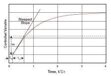
To estimate optimum controller settings requires some knowledge of process parameters, obtainable through design information or dynamic testing or both. Most tuning procedures are based on open-loop information, which includes estimated process gain, dead time and time constant—three process parameters. The most prominent pioneers in this field, John Ziegler and Nathan Nichols, estimated only two properties of an open-loop step-response (See “Optimum Settings for Automatic Controllers,” Trans. ASME, Nov. 1942) as described in Figure 4. Realizing that many slow processes would require too much time to reach steady state following a step upset, they elected to omit an estimate of steady-state gain. This makes sense, in that reaching within 1% of the steady state for a distributed lag requires an elapsed time of 4Στ, which for a 100-tray column would be 28 hours. Management is unlikely to accept such long intervals of open-loop operation, and other disturbances are likely to develop during the wait, as well.
Analyzing the step response
of a distributed process.
Instead, they approximated the response curve with two straight lines as in Figure 4, one a tangent to the curve at its steepest slope, and the other, a zero-response line ending at the zero-intercept of the tangent. The time at which the intercept is reached is considered estimated dead time, τde. Ziegler and Nichols then measured the slope of the tangent in terms of percent-per-minute, and compared it with the size of the step input. Their method can be simplified somewhat by marking the size of the manipulated-variable step Δm in percent of scale against the tangent, also in percent of scale. In the example of Figure 4, the process steady-state gain exceeds unity, in that the net change in the controlled variable exceeds Δm, but in some cases it could be less than unity. The time required for the controlled variable to respond an amount equal to Δm if it were to follow the tangent is its estimated time constant τ1e.
This method is applicable only theoretically to a non-self-regulating (integrating) process, where the controlled variable would continue to follow the tangent indefinitely. But it turns out to be a very effective method for estimating the parameters of a distributed lag because of the singularity of its response curve. As it happens, the two parameters needed to define the distributed process, steady-state gain, Kp, and response time, Στ, are directly related to the features of the response curve as estimated above:
Ziegler and Nichols found that closed-loop testing under proportional control can produce still more-accurate estimates of controller settings. In this method, they reduced the controller to effectively proportional-only action by setting derivative time to zero and integral time to maximum. They then reduced the proportional band incrementally until a uniform oscillation was produced. From this simple test they obtained two pieces of information: the proportional band that produced the sustained oscillation and the period of the oscillation.
Under these conditions, a distributed process will oscillate uniformly with the proportional band in percent set at 8.5Kp, and the resulting period of oscillation is observed to be 0.643Στ. The process parameters are then:
where Pu is the undamped proportional band and τu is the period of the undamped cycle.
It is often possible to calculate these parameters from known process information, when available, which can avoid testing, and even give valuable insight into the potential for parameter variations. For example, consider a stirred tank used for blending ingredients to a controlled composition. It can be modeled as a distributed lag whose response time Στ equals the residence time of the vessel, V/F, volume divided by flow rate. Steady-state gain, Kp, is the product of valve, process and transmitter gains. As an example, consider temperature control of an air-conditioned space against an ambient of 90 °F. If it is known that maximum chilling reduces the room temperature to 60 °F, and the range of the temperature transmitter is 50 °F to 100 °F, then Kp = (90 – 60)/(100 – 50) = 0.60.
Variable-Parameter Processes
A process with a fixed volume, V, will have a residence time that varies inversely with flow, F, through it. This is the case for the stirred tank described above. However, its steady-state gain also varies with flow in the same proportion. Consider, for example, an incremental flow of brine added to a given flow of water to produce a measured increase in salt concentration of the blend. If the water flow is then reduced by half, the same step change in brine flow will produce twice the change in salt concentration as before. Because the gain- and residence-time parameters change together, there is no net change in the slope of the response curve at its steepest point. If the estimated dead time remains the same, being determined by the mixer, there will be no need to change the tuning of the controller as flow changes.
Heat exchangers are more problematic in this respect. Their residence time and gain also vary inversely with flow for the same reasons as the stirred tank, but most exchangers have no internal recirculation as does a stirred tank. Their estimated dead time then also varies inversely with flow, making them much more difficult to control as flow decreases. The loop gain of a process is directly proportional to Kpτde/Στ. When all three parameters vary inversely with flow, the loop gain will vary, unless some form of compensation is applied. Suitable gain compensation is available in the form of the equal-percentage valve characteristic, whose gain varies directly with flow delivered. As a result, equal-percentage valves are recommended almost universally for temperature control. Integral and derivative settings should also be scheduled inversely with flow for compensation to be complete.
Another once-through process is the static mixer—a hollow pipe fitted with vanes or baffles providing radial mixing of the fed ingredients into a uniform blend at the exit. Longitudinal mixing is intentionally avoided, with the result that the static mixer’s dynamic response is dominated by dead time. In practice, it behaves much like a series of 20-50 noninteracting lags as described in Figure 2, but its parameters Kp and Στ vary inversely with flow like a heat exchanger. Here too, scheduling of controller settings as an inverse function of flow is necessary for complete compensation. A more effective solution is to install a circulating pump—the static mixer then behaves like a stirred tank.
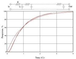
Distributed processes require special tuning rules.
Controller Tuning
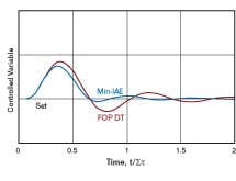
Rules for optimum tuning of PID controllers on distributed processes differ somewhat from those applied to first-order-plus-dead-time (FOPDT) models. Figure 5 compares the load response of a distributed process with an interacting PID controller tuned for minimum integrated absolute error (Min-IAE) against what would be Min-IAE tuning applied to a FOPDT model of the same process. In general, FOPDT tuning applies a wider proportional band along with shorter integral and derivative time settings than are optimal for distributed processes. Minimum-IAE settings are listed in Table 1.
The last column in the table is a measure of integrated error (IE) in the controlled variable per unit change in controller output Δm required to respond to a disturbance. IE can be related to operating cost such as excess energy applied or excess product giveaway, and is slightly less than IAE in a well-damped loop. IE/Δm is readily calculated as the product of the proportional band and integral time of the controller.
TABLE 1An example of an application of the tuning rules would be the temperature controller for the air-conditioned space describer earlier. The optimum proportional band for the PI controller would be 20Kp or 12%. If the band were depressed further to about 5%, a uniform oscillation would develop. Integral time could then be set at about 0.54 (1.55) or 0.84 times its period.
In conclusion, the distributed process—while undeniably complex—can be defined by only two parameters, and is relatively easy to control.
| About the Author |
F.G. Shinskey is a process control consultant based in North Sandwich, N.H.
About the Author
F.G. Shinskey
F.G. Shinskey

Leaders relevant to this article:
