Fieldbus in biopharma applications, Part 1
Genzyme Corp. recently installed a multiple-fieldbus control system platform at its pharmaceutical manufacturing facility in Allston, Mass. This plant produces enzyme-replacement therapies for rare lysosomal storage disorders (LSDs), which are classified as orphan diseases. The Allston site was built approximately 12 years ago with a conventional distributed control system (DCS) that’s used for manufacturing two enzyme replacement therapies. These drugs include Cerezyme for Gaucher’s disease and Fabryzyme for Fabry’s disease.
The new multi-bus control system is exclusively for manufacturing Myozyme, which is a drug therapy for Pompe’s disease. We renovated an existing manufacturing suite to facilitate the new process equipment and multi-bus control system.
Process areas included in the multi-bus control system include mammalian cell culture, purification, clean-in-place (CIP) and steam-in-place (SIP). Bus technology has been deployed on skid equipment, which includes bioreactor skids, chromatography skids, ultra-filtration skids, and CIP skids. Also, bus technology has been deployed on stick-built fixed vessels, associated piping, and transfer panels. Fieldbus protocols included in the facility are Foundation fieldbus, Profibus-DP, AS-interface (AS-i), and DeviceNet.
This was our first introduction to bus technology at Genzyme, and our subsequent selection of fieldbus technologies was based on the process equipment needs in a cell culture and protein purification manufacturing environment. We use fielbuses in process areas, which are electrically-rated as general purpose and Class 1, Division 2. We’ll highlight issues associated with using bus technology in each of these areas. We’ll also talk about fieldbus implications for facility constructability, software design, commissioning, metrology and calibration, validation, and maintenance.
Which Fieldbus Where?
During the preliminary design phase for building the new Myozyme manufacturing suite, we asked our design team, which included Genzyme personnel, a systems integrator, and our construction/engineering firm, to evaluate fieldbus as a viable technology. We felt fieldbuses might offer our project value that we couldn’t get from a conventionally instrumented system. We knew our process space was limited, and that we’d need to minimize the space that controller cabinets would consume to maximize space for process equipment. We also looked at fieldbuses as a way to reduce controller cabinet size, cable count, and conduit sizes and quantity. This all seemed quite appealing initially, and now I’d say bus technology did achieve our space-saving goal. Other attributes of fieldbuses, such as their capability to help with predictive maintenance, weren’t as tangible at the outset, but could be explored and exploited after startup and commissioning. The main task at the outset was to have all this equipment fit in the space available, and fieldbus technology was a means to this end.
We selected DeltaV from Emerson Process Management as the host controller, primarily for its batch capabilities. DeltaV is fieldbus-ready for the following fieldbuses: Foundation fieldbus, Profibus-DP, AS-i, and DeviceNet. The project’s total I/O count was approximately 4,000 points.
Our collective assessment revealed that fieldbus instrumentation availability was adequate when our project began in early 2003. Pressure, temperature, flow, pH, conductivity, level, and modulating control valve applications were well-represented fieldbus options. However, there were some instruments, which measure dissolved oxygen (in-situ measurement for bioreactors), vessel weight (strain gauge type), and UV analyzers (for liquid chromatography), that weren’t available in fieldbus versions. This obstacle could be overcome with 4-20 mA current-to-fieldbus converters. Also, mass flow controllers, which are used extensively with bioreactor equipment, weren’t found to be Foundation fieldbus ready, but were available with a Profibus-DP interface. Since it appeared that two fieldbuses would be required to address the traditional analog-type signaling, we selected Foundation fieldbus and Profibus-DP.
Open/close valves and discrete input devices deployed in a general-purpose, electrical environment were easily addressed with the simple AS-i bit-bus. There were many opportunities for actuating rising-stem or quarter-turn valves, which are used primarily for sanitary diaphragm valves and quarter-turn ball valves. Also, AS-i was used for discrete input devices, such as valve limit switches and proximity switches found on process transfer panels. Though simple in its implementation, we recognized early that AS-i would require a close eye to make sure we didn’t exceed its segment-length criteria. Typically, this is 100 meters, and then it’s time to add a repeater and power supply, and then extend another 100 meters. This could be repeated one more time for a total of 300 meters per segment. We didn’t recognize the length limit as a non-starter because most of the valves are clustered in close proximity to one another, especially on skid equipment, and so we embraced this bus for most of the discrete I/O requirements.
However, AS-i bus isn’t suitable for use in electrically classified process spaces due its high power requirements. Open/close valving and discrete input devices in electrically classified environments were addressed with intrinsically-safe remote I/O using Profibus-DP.
Either Profibus-DP or DeviceNet could address single-speed and variable-speed motors, and there are many of these in biopharmaceutical processes. We chose DeviceNet primarily on the merits of the host system having a rather nice graphical interface that allowed configuration of any node device at the host location. Examples of drive configuration at Genzyme include the need to configure full-load amps for overload protection, acceleration and deceleration ramp rates, stop modes of coast or ramp, etc. Troubleshooting drive issues was also available with the host DeviceNet interface.
Consequently, we embarked on a design with four fieldbuses. At the outset, this seemed like the best choice given the diversity of I/O types. We later discovered that our first introduction to a bus I/O infrastructure would teach us to include other factors when considering a multi-bus platform. Though I believe we have a technically solid I/O subsystem with our four fieldbuses, there’s probably a more optimal design approach if one considers the troubleshooting, maintenance, spare parts, and training aspects of each bus, which are unique. Clearly, one fieldbus doesn’t get us there, but maybe someday that will be a reality. I think, at best, given the timeframe of our project, we could have reduced the bus count to three, and, today, maybe to two. Live and learn.
Perhaps more important is the advance of technology in the past two years for increased bus devices, as well as some fundamental bus topology advances with AS-i. For example, this bus can now extend 300 meters without repeaters, and instead uses a bus tuner that sits at the end of the segment to obviate earlier length limits.
We also know that fieldbus instrumentation is more expensive from an initial purchase standpoint. We didn’t track our construction costs in a way that would allow us to say with certainty that we realized installation savings. We believe that it should have been less costly due to smaller controller cabinets, fewer field cables, and fewer conduits. Our perception is that the overall cost was less, but we don’t really know by how much. I think our biggest savings are still yet to come with the predictive maintenance model inherent in Foundation fieldbus. Foundation fieldbus transmits device status along with the process variable, so it’s possible to receive device health information regarding imminent instrument failure. In the biopharm industry, this could mean the difference between a successful multi-day or month batch run and a failure, which could run into the millions of dollars in lost product. Therefore, this is the cost savings on which we’d rather focus our attention.
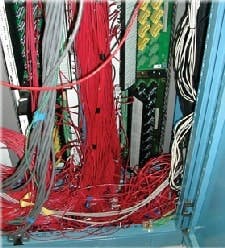
A conventional wiring system would have meant over 230 wires to each reactor. (Click image to enlarge.)
Fieldbus Architecture
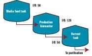
The following example shows how Genzyme’s multi-bus architecture was deployed in one of our process suites. Figure 1 shows a typical bioreactor train, which comprises a media feed tank, bioreactor, and harvest tank with their I/O requirements. If this bioreactor train had been conventionally wired, a combined total of 238 cables would have been pulled between a controller cabinet and the process equipment.
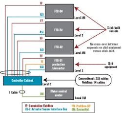
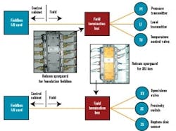
Figure 2 below depicts a cable block diagram for a fieldbus implementation of this same bioreactor train. You’ll notice that there’s a dramatic reduction in the cable quantity; only 14 home-run cables are required between the controller cabinet and the field terminal boxes (FTBs). These FTBs are strategically located in the process suite close to the process vessels to minimize instrument cabling that fans out from the FTB to each instrument.
FIGURE 2: FIELDBUS WIRINGFTB-B1, which wires to the bioreactor skid, includes two Foundation fieldbus segments, two AS-i segments, and one Profibus segment. The segments don’t extend beyond the bioreactor to other vessels, even if they had instruments nearby these segments. This was done by design to maintain segment segregation between skid equipment, such as bioreactors and field assembled fixed tanks. Bioreactors are the only process skids that use redundant instrumentation, specifically, dissolved oxygen and pH measurement. These redundant instruments share the same segment. We didn’t design for redundant segments in this case because a bioreactor is unique in that you must have all instruments and valves functional. If not, you shut down the reactor. The redundant transmitters provide assurance that we’ll likely have at least one operational by the end of a bioreactor run, even if there’s a sensor failure or probe fouling on one of the two. Sensors can’t be changed underway because they’re within the sterile boundary of the reactor.
Conventional wiring takes up lot of space.
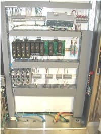
The fieldbus architecture lends itself to maintaining an orderly appearance to controller cabinets. Figure 3 below represents one of our typical conventionally wired control systems, and Figure 4 (below) is typical of fieldbus. This cabinet uses five bus I/O cards that communicate with approximately 200 I/O points.
Fieldbus Segment Design
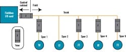
The buses selected for our facility also fall into two distinct categories—a powered bus and an unpowered bus. The powered buses include Foundation fieldbus and AS-i bus. The unpowered buses include Profibus-DP and DeviceNet. The powered bus includes the communications and device power on the same wires.
The FTBs would house this short-circuit protection equipment for field devices of both powered buses, and we hoped to identify a common short-circuit device type that could be used for both Foundation fieldbus and AS-i. At the time of our detail design effort, Relcom offered its Spurguard for Foundation fieldbus. We’d also hoped to find something in a similar form factor for AS-i. At our request, Relcom designed and manufacturing a Spurguard for AS-i, which enabled our powered buses to have the same look and feel. Figure 6 below illustrates where he Relcom’s Spurguard devices are located.
FIGURE 5: CHICKENFOOT!Our project’s ultimate goal was to have the stick-built process equipment, which included vessels, transfer panels, and skid equipment using an identical segment design approach. This allowed us to develop segment design standards that were followed by our engineering design contractor for the stick-built process equipment and by the various skid vendors.
FIGURE 6: SPURGUARD TO THE RESCUE!Are Fieldbuses Right for Biopharma and You?
CRITERIA used for assessing the viability of fieldbuses include the following:
- Instrumentation availability: are instruments typically found in a biopharm facility available with fieldbus?
- Bus selection and bus quantity: would it require two, three, or four fieldbuses to address the various I/O types?
- Electrical classification: could bus instrumentation be deployed in electrically hazardous environments?
- Cost: is bus implementation more expensive? If so, is there payback over time based on a predictive maintenance model (inherent in bus systems) compared to our present run-to-failure?
| About the Author |
