I was recently sorting through some old computer files when I found a Lotus 1-2-3 file that I'd used as a model when developing a DOS control valve sizing application for Hammel Dahl in 1987. I also found a Windows XP laptop that has a version of Excel that can read Lotus 1-2-3 files.
The 1985 version of ISA S-75.01 included the same equations for the effect of pipe reducers as is found in the current version of the standard. The 1985 version of the standard doesn't make any recommendations as to how to apply the reducer corrections (which include the valve coefficient, CV as one of the input parameters). Incorporating CV as a parameter in the valve sizing calculation complicates the calculation because CV is the quantity that one wants to calculate. The only way I could see to calculate CV when it was one of the required input parameters was to use an iterative solution. This is exactly what later versions of the standard do. They even suggest methods for performing the iterative solution.
My first attempts at iterative solutions in 1987 for liquid flow worked well, but calculating with my old DOS PC took a painfully long time. After experimenting with simply calculating pressure losses in reducers, I came up with the method in my 1987 Lotus file that I’ll describe here. I don’t claim to have invented anything, and I'm sure others have thought of it, but I've never seen it published anywhere.
If one wants to be able to do accurate hand calculations, or construct a simple program or Excel sheet, the method described here gives answers that agree exactly with iterative calculations using the equations in the current version of the ISA and IEC standards and in a small enough space to fit into this short article. The method described here only applies to turbulent, liquid flows.
This calculation method is based on formulas for k factors of sudden expansions and contractions and for pressure losses through fittings found in Crane Technical Paper No. 410. Flow of Fluids Through Valves, Fittings and Pipe.
Table 1 is an Excel worksheet that implements the calculations. To construct the worksheet, start by entering the text shown in Columns A, B, C and E, rows 3 through 24. The formulas for all the calculations rely on the cells in Column D, having the names to their left in Column C. To name them, highlight Columns C and D, rows 6 through 23. Select the “Formulas” tab, select “Create from Selection,” check “Left column,” and click “OK.” Now all the cells in Column D, rows 6 through 23, will have the names in the cells to their left. This makes it possible for all the formulas to use the actual names of each variable, instead of simply cell references. For example, the flow appears in all the formulas that depend on it as “Q” instead as simply “C6.”
| A | B | C | D | E | F | |
| 1 | CONTROL VALVE SIZING WITHOUT ITERATION: LIQUID | |||||
| 2 | Demo: Full port ball valve, 100% travel | |||||
| 3 | Unit | Name of cell to the right | User input and calculated formulas | |||
| 4 | ||||||
| 5 | Given process data | |||||
| 6 | Flow | gpm | Q | 8,069.672181 | User input | |
| 7 | Inlet pressure | psia | P_1 | 100 | User input | |
| 8 | Pressure drop | psi | DELTA_P | 3.107 | User input | |
| 9 | Specific gravity (p1/p0) | G | 1.00 | User input | ||
| 10 | Vapor pressure | psia | P_V | 1.00 | User input | |
| 11 | Critical pressure | psia | P_C | 3,208 | User input | |
| 12 | Recovery factory | F_L | 0.27 | User input | ||
| 13 | Line size | inch | D_LINE | 24 | User input | |
| 14 | Valve size | inch | d_VLV | 12 | User input | |
| 15 | ||||||
| 16 | Formulas See Line: |
|||||
| 17 | Calculations | |||||
| 18 | Δp across inlet reducer | psi | DP_IR | 4.3004 | Intermediate Calc | 27 |
| 19 | Press upstream of valve | psia | P1_VLV | 95.6996 | Intermediate Calc | 28 |
| 20 | Press loss inlet plus outlet reducers | psi | DP_REDUCERS |
2.9772 |
Intermediate Calc | 29 |
| 21 | Pressure drop across the valve | psi | DP_VLV | 0.1298 | Intermediate Calc | 30 |
| 22 | Choked press drop that applies to the valve itself | psi | DP_CHOKED_VLV | 6.9069 | Intermediate Calc | 31 |
| 23 | ΔP to be used in calc. of required Cv | psi | DP_SIZING | 0.1298 | Intermediate Calc | 32 |
| 24 | Required Cv | 22400.0000 | Final Result | 33 | ||
| 25 | ||||||
| 26 | Formula in column D | |||||
| 27 | =(0.5*(1-(d_LV^2/D_LINE^2))^2+1-d_VLV^4/D_LINE^4)*(Q^2*G/(890*d_VLV^4)) | |||||
| 28 | =P_1-DP_IR | |||||
| 29 | =(1.5*(1-(d_VLV^2))^*2(Q^2*G/(890*d_VLV^4))) | |||||
| 30 | =DELTA_P-DP_REDUCERS | |||||
| 31 | =F_L^2*(P1_VLV-P_V*(0.96-0.28*SQRT(P_V/P_C))) | |||||
| 32 | =IF(DP_VLV | |||||
| 33 | Q*SQRT(G/DP_SIZING) | |||||
Table I: This Excel spreadsheet implements a non-iterative approach for sizing control valves for liquid, turbulent flows.
Type the formulas into Column D, rows 17 to 24. For convenience, the formulas have been printed in boldface type in rows 26 through 33. It's these formulas entered in D, 17-24 that do the actual calculation. These are the exact formulas shown in Table 1, but in the form required by Excel.
As a check on your work, enter the values in Column D, rows 6 through 14. The results of the intermediate and final result should agree exactly with those shown in Table 2.
Table 2 shows some typical calculations that confirm this non-iterative method yields results that agree exactly with an iterative calculation that uses equations in ANSI/ISA-75.01.01-2012 and IEC 60534-2-1.
| Comparison Liquid control valve sizing by iterative and non-iterative methods |
||||||||
| Valve | Line size | Flow, gmp | P1, psia | ΔP, psi | % travel | Cv, Iterative | Cv, Non Iterative | |
| 12" Full port ball | 24" | 32,908.0025 | 100 | 60 | 100 | 22,400.00002 | 22,400.0002 | Choked |
| 12" Full port ball | 24" | 8,069.6722 | 100 | 3.107 | 100 | 22,400.0000 | 22,400.0000 | Non-Choked |
| 3" Parabolic globe | 6" | 420 | 46.7 | 20 | 99.2 | 99.1731 | 99.1731 | Non-Choked |
| 3" Segment ball | 6" | 1,040 | 46.7 | 20 | 97.9 | 409.6483 | 409.6483 | Choked |
| 6" Segment ball | 12" | 880 | 50 | 25 | 50 | 178.0285 | 178.0285 | Non-choked |
Table II: A comparison of non-iterative solution results with iterative approach described in ANSI/ISA-75.01.01-2012 and IEC 60534-2-1.
I've seen several places in the literature, including Crane TP 410, that the value of CV used in the reducer corrections is the 100% open CV of the valve. ANSI/ISA-75.01.01-2012 and IEC 60534-2-1 are very clear that this is not the case, and that the value of CV to be used in the reducer calculations is the calculated CV based on the given process conditions. If this weren't so, there would be no need for a suggested iterative technique in the standards.
I've tried using the same approach as described above for compressible flow, but the results were disappointing. Advanced control valve sizing methods are only as effective as the accuracy of the process data used.
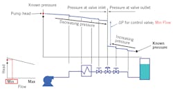
Figure 1: Example analysis of control valve sizing pressure drop at the minimum specified flow.
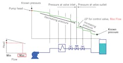
Perhaps the most misunderstood area of control valve sizing is the selection of the pressure drop, DP, to use in the sizing calculation. DP can't be arbitrarily specified without regard for the actual system in which the valve will be installed. What must be kept in mind is that all the components of the system except for the control valve (pipe, fittings, isolation valves, heat exchangers, etc) are fixed and at the flow rate required by the system (to cool a hot chemical to a specified temperature, maintain a specified level in a tank, etc). The pressure loss in each of these fixed elements is also fixed. Only the control valve is variable, and it's connected to an automatic control system. The control system will adjust the control valve to whatever position is necessary to establish the required flow (and thus achieve the specified temperature, tank level or whatever). At this point, the portion of the overall system pressure differential (the difference between the pressure at the beginning of the system and at the end of the system) not being consumed by the fixed elements must appear across the control valve.
Let's assume you need to size a control valve for a system that's been designed but not yet built, or perhaps a system that's running, but it isn't possible or convenient to get reliable pressure measurements near the control valve. The correct procedure for determining the pressure drop across a control valve at the flow rate for which you plan to perform a sizing calculation is as follows: start upstream of the valve at a point where the pressure is known (for example a pump where the pressure can be determined from the head curve), and subtract the pressure loss in each of the fixed elements. When you get to the valve inlet you know P1 is the pressure immediately upstream of the valve. At this point, you can't directly calculate the pressure drop across the valve because you have yet to determine its size and the percentage of opening at which it operates. The next step is to go to a point downstream of the control valve where the pressure is known (for example, a tank where the head is known), and then work upstream toward the control valve, adding the pressure loss of each of the fixed elements (you're adding the pressure losses because you're working in the direction opposite to the flow). When you get to the valve outlet you know P2 is the pressure immediately downstream of the valve. The actual pressure drop across the control valve is the difference between the upstream and downstream pressures, that is DP = P1 – P2. The above process is depicted in Figures 1 and 2. If you plan to perform sizing calculations at more than one flow rate (for example, at both maximum and minimum design flows), you must repeat the calculation of P1 and P2 at each flow rate because the system pressure losses (and pump head) are dependent on flow. With realistic pressure drop data determined as above, along with your other process data, you can use state-of-the-art control valve sizing software to size your control valve correctly for the application to ensure optimal control while reducing noise and valve wear.
Figure 2: Example analysis of control valve sizing pressure drop at the maximum specified flow.
Behind the byline
Jon F. Monsen, Ph.D., P.E., is a control valve technology consultant for Valin Corp. with more than 30 years’ experience. He's lectured nationally and internationally on the subjects of control valve application and sizing, and is the author of the chapter on “Computerized Control Valve Sizing” in the ISA Practical Guides book on Control Valves. He's also the author of Control Valve Application Technology: Techniques and Considerations for Properly Selecting the Right Control Valve.
About the Author
Jon Monsen
Valin Corp.

Leaders relevant to this article:


