How to know if the tuning or the valve is responsible for oscillations
This column is moderated by Béla Lipták, automation and safety consultant and editor of the Instrument and Automation Engineers' Handbook (IAEH). If you have an automation-related question for this column, write to [email protected].
Q: The level in our absorber in a vapor recovery unit is maintained by adjusting an outlet control valve with a PID loop. The loop is held in manual at zero percent output (valve closed) until the gasoline return pump comes on. The loop output is manually moved to 65% for a couple of seconds, and then the loop is switched to automatic. The loop is in a Allen-Bradley SLC 500 controller and has dependent gains. At present, the loop is tuned for a proportional gain of 5; the integral gain (minutes per repeat, smaller number means bigger action) is 2; and derivative is unused/zero.
Everything works fine except that the process variable (PV = level measurement) and the control variable (CV = controller output ) oscillate. I found an article by Greg McMillan explaining that the proportional gain should be raised, not lowered, to address this. I tried to follow his advice, raising the proportional gain from 1 to 5. As a result, the oscillation of the PV decreased to the point where it's no longer a concern. On the other hand, the CV is still oscillating.
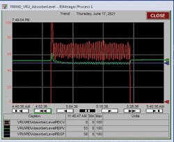
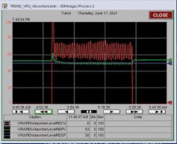
Figure 1: Operation with tuning settings of Kp = 10, Ki = 2 and Kd = 0. Measurement (green) oscillation is OK, but valve oscillation (red) is unacceptable.
I tried a proportional gain of 10 (leaving reset as is at 2). This degraded the control as shown in Figure 1. So, I returned the proportional gain to 5, and that's how we’re running today.)
The valve is a brand-new, 3-inch ball valve with an RCS SCC-10 electric actuator and smart controller. I've also experimented with increasing the integral to Ki = 10 minutes, which improved both oscillations a little, but the system just stopped (the pump shot off). The question is: will it hurt the valve to oscillate as shown in Figure 1 (20% every minute) or is it fine? If this amount of oscillation is unacceptable, what should we do and what tuning settings would help? Do you think the valve is defective or that we have installation issues?
William Love
[email protected]
A1: If your valve is on the discharge side of a constant speed pump, you're wasting pumping energy when throttling the valve. In the future, use no valve and throttle the speed of a variable speed pump. Also, it's not clear why the absorber level needs to be constant. If it doesn't, you can treat the absorber as a "surge" tank that accepts a variable inflow from an upstream source, then delivers a more constant flow to the next stage.
This can be done if the level is allowed to float up and down a little around the setpoint, as a function of the proportional setting. Integral you can reduce a lot (10 or more) or eliminate. An alternate approach is to use one setpoint that's at the lower-level limit and set the controller bias to zero. This way, the level can't fall below that low limit, but is allowed to rise to the high limit, which is set by the proportional band.
Level is a process that integrates the difference between the incoming and outgoing flows. Using integral in the PID algorithm of a level controller is seldom recommended because two integral components in series result in oscillation.
You didn't say if your valve has a positioner to keep the load variation or valve-related variations (characteristics, non-linearity, deadband, sticking) out of the level loop. Level control requires a linear valve, and because a ball valve isn't linear, using a positioner is preferred. If you do have a positioner, you have a cascade loop with level being the primary controller and valve position being the secondary. In that case, the positioner (the secondary controller) must be strong and an order of magnitude faster than the primary. If you don't have a positioner, that's a problem. And, if the actuator is for an on-off valve, you have an even worse problem because on-off actuators are undersized and therefore slow.
Electric motor actuators are usually too slow and their deadtime results in cycling.
Béla Lipták
[email protected]
A2: I'd suggest that you check the valve. A control loop responds after an error is detected, so response is delayed. The delay means that a process accumulates error, the controller reset action accumulates error, and even signal delays add to the lags. Errors accumulate until the valve responds and the process can adjust. In other words, control is always late. No valve is perfect, but the delay in response coupled with an integrating element means the loop will oscillate at the resonant frequency. Reducing packing friction, installing a stronger actuator, making sure that the air supply pressure doesn't drop during valve movement, and improving the positioner are all factors that affect valve performance. Inspect the valve for a loose connection between the valve stem and the positioner, pinched air tubing, plugged air supply filter—anything which could impact its operation. As for damage to the valve, packing wear is increased, but this is usually not a problem.
Twenty percent cycle is excessive for control. As for wear, I wouldn't worry. You haven't indicated the pressure drop across the valve. Does it have a generously sized actuator?
Does it have a good positioner? An actuator sized for on/off service will usually be slow in control service. When valves are selected based on price, the provider can reduce costs by using a smaller actuator. You really need a positioner.
I suspect that you're seeing the effects of either slow or stick-slip action. Include any source of integration, and oscillation will happen. This is so bad I'd look for a sloppy connection between the valve linkage and the positioner, or any slop in the linkage between actuator and valve stem. The chart showing constant amplitude cycle is classic for a valve jumping back and forth between positions.
Can you observe the valve in action? Can you observe the valve linkage and the positioner gauges?
If the normal valve position is near closed, then the very non-linear forces on the valve disc make accurate position difficult. For background, refer to ISA S75.25.01 for testing and TR 75.25.02.
Cullen Langford
[email protected]
A3: The persistent oscillation with constant amplitude that is significantly decreased as the PID gain is increased is symptomatic of a limit cycle caused by backlash and/or stiction in the control valve. If the valve was simply slow in responding, the oscillations would have gotten worse with a higher PID gain. Ball valves tend to have appreciable amounts of backlash from the play in linkages to convert vertical actuator shaft motion to rotary ball motion and from pinned or keylock connections of shaft to ball stem and the ball stem to ball. There is also significant stiction from packing friction and seal friction designed for tight shutoff. The result can be shaft windup and positioner readback that is not representative of actual internal ball position. A sensitive low noise flow measurement is needed to do an inline open loop test to see how the valve responds for small signal changes. If the valve is removed and tested in a shop, a travel gauge can be installed on ball to detect actual ball movement. Note that backlash causes limit cycles if there is two or more integrators anywhere in the system whether it be the process (e.g., level), or in the automation system (e.g., integral action in positioner, integral action in PID). There are some PID options that can reduce the oscillation from backlash (e.g., integral deadband and external-reset feedback).
To reduce limit cycles by minimizing backlash and stiction in ball control valve design, use diaphragm actuators, splined shaft to stem connections, integrally cast ball stem, ultra low friction packing, and minimal seal surface on ball.
The proposed Annex A for ISA 75.25.02 has equations to show you how PID gain reduces limit cycles from backlash and stiction: Valve-Response-and-Control-Loop-Performance-TR76.25.02-Annex-Proposal-Rev03.pdf (controlglobal.com)
The following Control articles also provide much more information:
Responsible control valve response (controlglobal.com)
How to specify valves and positioners that don’t compromise control (controlglobal.com)
Control Systems: Is Your Control Valve an Imposter? (controlglobal.com)
Feel free to ask me any questions for more detail. Perhaps you would like to join the ISA Mentor Program I am leading at: ISA Mentor Program ?
Gregory K. McMillan
[email protected]
A4: This is a perfect example of why PID is almost always incorrectly tuned for level control. Level is an integrating process, and you're inserting additional integration via the integral function of the PID. This is causing oscillation of the output. Better tuning of this level control loop is to dial back almost all of the integral action, e.g., raise the integral to 10 or more minutes per repeat. Leave the proportional gain alone or adjust it to keep the level from swinging to extremes. The level should slowly rise and fall about the setpoint, but never be at setpoint for long. However, the output should no longer oscillate.
Control valves aren't meant to oscillate; we call it hunting or chatter. It wears out the packing and seals. In my CAP preparation classes, I teach level control as a unique topic in the control tuning section. My advice is to depend on proportional control with perhaps just a little bit of integral and never any derivative.
Dick Caro
ISA Life Fellow, Certified Automation Professional (ISA)
[email protected]
A5 (with questioner responses): It's hard to see from here. Is the valve controlling the flow at the discharge of a pump? Yes, the pump is about three feet before the valve.
If not, is the vapor recovery unit pressure in control? There is no pressure loop. Before I put in this loop, I'm asking about it. It was on/off control with an on/off valve.
What is the amplitude of the controller output oscillation? Amplitude lightly less than 20%. Period approximately one minute.
What type of valve is being used? It's a brand new, 3-in., 100-30 [Cla-Val Powercheck] control valve.
It looks like integral time is too short, but if the problem is the valve, then this will not make much of a difference. The valve may have stiction and/or backlash. Even if it is new? What do you do about that?
Sigifredo Nino, P.Eng.
CEO and Process Control Expert
Summa Control Solutions Inc.
[email protected]
A6: I've read of a number of successful P-plus-I tunings, where the final settings were based on the “critical” settings at which closed-loop oscillations begin.
Gerald Liu
[email protected]


