This column is moderated by Béla Lipták (http://belaliptakpe.com/), automation and safety consultant, who is also the editor of the Instrument and Automation Engineers' Handbook (IAEH). If you would like to become a contributing author of the 5th edition of the 1st volume, to be published in 2015, or if you have an automation-related question for this column, write to [email protected].
My query is this: In which applications should we consider the use of the analog heat detection cable and in which the digital heat detection cable? Could you please clarify?
Loganathan Ethiraj
[email protected]
A: This type of cable is not used for measurement. It is used for fire protection. The digital version is more like a fuse that melts when a prescribed temperature is met. The analog version is based on either a thermistor or a thermocouple. The thermistor version generally is used once and is done. The thermocouple version, if manufactured with the correct materials, can last through a fire, but is never as good afterwards as a pristine sensor. The thermocouple version is like standard thermocouple sheath material with no hot junction. Instead it has carbon-based filler material that becomes conductive (making a semi-junction) when exposed to extreme heat. Neither of these will tell you where along the length the fire is located and, in any case, is unsuitable for temperature measurement.
Frank L. Johnson
[email protected]
A: In our projects, we used digital-type, heat-detection cable for some storage tanks and cellars of electrical substations. Digital cable can work for high temperatures and long distances (10,000 m) as compared to analog cables (1000 m). There is a site where you can find more information.
Harvindar S Gambhir
[email protected]
Q: As shown in Figure 1, I have to do an independent partial valve stroke test per IEC 61511. I have to do this test for both a PLC/DCS controller and SOV combinations, and a partial stroke test for pneumatic actuator and valve combinations.
Figure 1. A reader wants to know how to do partial stroke testing for both DCSs and for SOV combinations.
What are the available methods to perform these partial stroke tests for my ESDV valves?
A M.Ulaganathan
[email protected]
A: There are two tests that need to be performed:
- Partial stroke of the valve. This is done through a command from the PLC, which moves the valves slightly and gets feedback that valve has moved from 100% to 90% in general.
- Health of the SOV. This is to check that the SOV is opening by a pulse command from a PLC, and getting feedback of reduction of pressure on the actuator.
Harvindar S Gambhir
[email protected]
A: There are various solutions for partial stroke testing offered by different manufacturers. Some of them are mechanical and some are electronic. Metso, Emerson, Rotork, etc., provide electronic solutions. Please note that not all can provide diagnostics for SOV. You can refer to the VG9000 catalog for further detail.
Debasis Guha
[email protected]
A: There is no requirement in IEC 61511 for partial stroke testing of valves. However, if you wish to do it, there are over a dozen vendors with solutions that differ in many ways. The standards do not mandate that level of detail.
Paul Gruhn
[email protected]
A: I would suggest an online search on partial stroke valves. Several vendors have addressed the issues and offer hardware to make the partial stroke tests. Simply switching the valve and hoping to manually stop the valve is very likely to seriously upset the production people. This subject has been discussed and addressed for a decade. It is not new.
Cullen Langford
[email protected]
A: What is the correct way of representing an electronic remote sensor of a differential pressure measurement transmitter on a P&ID diagram? This question involves a Rosemount electronic remote sensor level transmitter. Rosemount supplied two transmitters with diaphragm seals that we mount to the vessel. The two transmitters communicate via a proprietary bus signal, and generate a single 4–20 ma signal which is representative of the vessel level and is fed to the control system.
I'm not sure if the interconnecting line between the two transmitters would be shown as an electrical signal or as a communication link as found on Table 5.3.2, No. 15 of the ANSI/ISA-5.1.-2009.
Larry Hoffman
[email protected]
A: For the latest ISA flowsheet symbols, you can review the 2009 revision of S5.0.1 (go to http://tinyurl.com/25wu25 for a link to ISA standards), but unfortunately, it doesn't clearly answer your question, just as it doesn't cover many more recent developments. I have been saying for years that updating the standard is much needed.
Béla Lipták
[email protected]
A: I'd suggest that the remote device be tagged as a PE (pressure element or sensor), and connected by a bubble-line to the PDIT. Communication is HART between the two devices, but calling it a PT tends to confuse. As you've no doubt noted, 5.01:2009 doesn't quite cover it.
Ian H Gibson
[email protected]
A: Since you didn't give any additional information, I assume it is a standard PDT with a loop-powered signal to the control system.
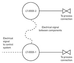
Yes, sounds like the 3051S ERS System, so you'd connect a dedicated com link as an electrical signal between the two instruments.
If I am correct, then the way to show it would be as shown in Figure 2.
Figure 2. Connect a dedicated com link as an electrical signal between the two instruments.
Alejandro Varga
[email protected]
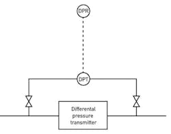
A: Based on your descriptions, I would draw it as shown in Figure 3.
Figure 3. Alternatively, the described system could be shown this way.
David Ubert
[email protected]
A: The connections from the high- and low-pressure detectors to the process device you can draw with fine line, and use bold through the auxiliary devices. Refer to Diaphragm, ANSI/ISA-5.1-2009, Table 5.2.5. The letter designation inside the transmitter bubble is PDT.
If you're also showing the manifold (using three to seven valves, depending your application), refer to Lipták, Process Measurement and Analysis Handbook, page 724, fig 5.2.j.
Francisco Alcala
[email protected]
About the Author
Béla Lipták
Columnist and Control Consultant
Béla Lipták is an automation and safety consultant and editor of the Instrument and Automation Engineers’ Handbook (IAEH).

Leaders relevant to this article:


