How to select control valves, Part 1
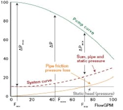
CONTROL VALVES modulate the flows of process or heat-transfer fluids, and stabilize variations in material and heat balance of industrial processes. They manipulate these flows by changing their openings, and modifying the energy needed for the flow to pass through them. As a control valve closes, the pressure differential required to pass the same flow increases, and the flow is reduced. Figure 1 (see below) illustrates the pump curve of a constant-speed pump and the system curve of the process that the pump serves. The elevation (static) head of the process is constant, while the friction loss increases with flow. The pressure generated by the pump is the sum of the system curves (friction and static) and the pressure differential (ΔP) required by the control valve. As the valve throttles, the pump travels on its curve, while delivering the required valve pressure drop.
The pumping energy invested to overcome the valve differential is wasted energy, and is the difference between the pressure required to “push” (transport) the fluid into the process (system curve, at bottom left, in Figure 1) and the pump curve of the constant-speed pump. Pumps are selected to meet the maximum possible flow demand of the process, so they tend to be oversized during normal operation. Consequently, using control valves to manipulate the flow generated by constant-speed pumps wastes energy, and increases plant-operation costs.
Therefore, when designing a control system, a process-control engineer must first decide whether a control valve or a variable-speed pump should be used to throttle the flow. Variable-speed pumps reduce flow by reducing pump speed. So, instead of burning energy unnecessarily introduced by the pump head, that energy isn’t introduced in the first place. This lessens operating costs, but increases capital investment because variable and constant-speed pumps usually cost more than control valves.
When several users are supplied by the same variable-speed pump, its speed can be automatically adjusted by a valve-position controller (VPC), which detects the opening of the most-open user valve (MOV). The MOV isn’t allowed to open beyond 80-90% because, when the set-point of the VPC is reached, this integral-only controller starts increasing the pump speed. This increases the available pressure drop for all the valves, which in turn reduces their openings.
FIGURE 1: PUMP AND SYSTEM CURVESValve Types and Characteristics
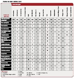
If the cost-benefit analysis comparing constant and variable-speed pumping systems favors using throttling valves, the next task is to select the right valve type for the application. Figure 2 (see below) shows that various valve designs have different pressure and temperature ratings, costs, capacities (Cd = Cv/d2), etc. Once the valve type is selected, the next task is to select the valve characteristics, and size the valve. These characteristics determine the relationship between valve stroke (control signal received) and the flow through the valve, while size is determined by maximum flow required.
After start-up, if the control loop tends to oscillate at low flows but is sluggish at high flows, users should consider switching the valve trim characteristics from linear to equal-percentage. Inversely, if oscillation is encountered at high and sluggishness at low flows, the equal-percentage trim should be replaced with a linear one. Changing the valve characteristics can also be done (sometimes more easily) by characterizing the control signal leading to the actuator rather than by replacing the valve trim.
| About the Author |
Béla Lipták is editor of the Instrument Engineer’s Handbook, and former chief instrument engineer at C&R (later John Brown). He is a recipient of ISA’s Life Achievement Award (2005) and member of CONTROL's Process Automation Hall of Fame (2001).


