Model-predictive control can solve valve problem
By Greg McMillan, CONTROL columnistIN THE OLD days, we used small and large valves with the idea that the small valve would extend the rangeability of the manipulated flow for low loads. The valves were split ranged with the split range point set at the classical value of 50%. The split range was typically done in the positioner. Of course, the big valve tended to get stuck in the seat where the friction was highest, especially if the valve was designed for tight shutoff or the plug stayed in the seat for long periods of time.
As a result, some ingenious engineers devised a scheme in which a pressure switch tripped and energized solenoid valves. This froze or closed the small valve, and preloaded a pressure to the big valve to get it off of its seat, so it could take over throttling the flow for high loads. These valves looked like a Christmas tree with the extra solenoids, switch, and tubing, but the instrument technician wasnt in the holiday spirit when maintenance was required. Getting everything right in the middle of the night, when a valve needed to be replaced to keep the plant running, was difficult. The failure rate was higher than a simple valve, which was not so bad considering the pneumatic positioner and pressure switch were out of calibration anyway after about six months operating in the plant. Since there was no readback of actual valve position in the control room, various creative explanations were offered for the increasingly pesky oscillations as the calibration and settings shifted. Then there were the persistent entertaining questions of split ranged gap and overlap.Early improvements
In the last decade, users got smarter, and installed digital positioners that would hold their calibrations. The split ranging in the field was now accurate, but configuration engineers preferred the maintainability, visibility, and flexibility of the standard splitter block on the controller output. A split range point other than 50% was readily implemented, and the actual valve positions were displayed for the operator. The split range point was set to compensate for the different valve sizes and gains. For example, if the big valve was about 10 times larger than the small valve, the small and big valves stroked from 0 to 10% and 10 to 100% controller output, respectively. Signal characterization blocks were added to linearize the installed characteristic of each control valve. Tricky configuration engineers devised and implemented valve-switching strategies that better addressed the transition at the split range point.BIG VALVES, LITTLE VALVES
| APPLICATION NOTE Implementing MPC to reduce variability by optimizing control valve response |
In the last decade, users got smarter, and installed digital positioners that would hold their calibrations. The split ranging in the field was now accurate, but configuration engineers preferred the maintainability, visibility, and flexibility of the standard splitter block on the controller output. A split range point other than 50% was readily implemented, and the actual valve positions were displayed for the operator. The split range point was set to compensate for the different valve sizes and gains. For example, if the big valve was about 10 times larger than the small valve, the small and big valves stroked from 0 to 10% and 10 to 100% controller output, respectively. Signal characterization blocks were added to linearize the installed characteristic of each control valve. Tricky configuration engineers devised and implemented valve-switching strategies that better addressed the transition at the split range point.
MPCs control the process variable by simultaneously manipulating the small and big valves.
If you could always use the small valve for a fine adjustment, you could solve the real problem, which is control valve resolution. Those innovative configuration engineers devised a valve position control strategy, in which an integral-only controller was added that manipulated the big valve to keep the small valve at 50% open. The split range was eliminated and the process controller just manipulated the small valve. Unfortunately, the valve position controller could not have proportional or derivative action, and the integral time setting needed to be five times larger than the product of the process controller gain and reset time to prevent interaction between the two loops. As a result, the valve position controller was too slow for big upsets or set point changes. Feed-forward action could be added, but unmeasured disturbances were still a problem and it was a challenge to explain the difference between a valve position controller and a valve positioner. The explanation that a valve positioner is the box on the valve didnt work anymore when fieldbus allowed valve positions controller to be in the field. In addition, there was a creative modification to the PID algorithm to move the big valve to share the load with the small valve, but it was a custom implementation that didnt address differences in valve dynamics or large dead times. Finally, engineers found that a small model predictive controller (MPC) could inherently solve these traditional valve problems without relying on split ranging, valve position control or custom solutions. In essence, an MPC is set up to control the process variable by simultaneously manipulating the small and big valves.For some MPC software, this is all that is required. For MPC software that requires controlled variables to equal the number of manipulated variables, the small valve is wired back as an additional controlled variable for optimization.SIMULTANEOUS THROTTLING OF FINE AND COARSE CONTROL VALVES
The MPC can solve the problem without split ranging, valve position control, or custom solutions.
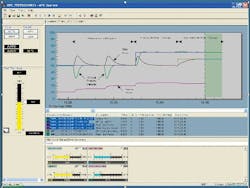
Figure 2 above shows how small (trim) and big (coarse) valves are simultaneously moved to compensate for load upsets and to meet set point changes. The default MPC tuning was used, except that the penalty on error for keeping the small (trim) valve at 50% was reduced by a factor of 10. This adjustment was made so optimization of this valve position was a lot less important than the control of the process variable. Even with this reduced penalty, the small valve still returned to 50% relatively quickly to be ready for the next adjustment.In addition, the MPC incorporated the knowledge of the difference in valve gains and dynamics in its process models, and eliminated interaction associated with simultaneous throttling. The MPC also facilitated feed-forward control with proper dynamics by adding disturbance variables, and was better able to deal with dead time dominant processes. The MPC further reduced the limit cycle from the resolution limit (stick-slip) of the big valve and offered the opportunity to eliminate it by freezing the big valve at its last position, which was when the process variable was within a band around the set point. The width of the band was the product of the big valves resolution and the big valves process gain.There are many opportunities to use fine adjustment valves to reduce process variability without the +60-year-old headaches of split ranged or valve position control. It is a fine time to break away from old valve problems and break into model-predictive control.SEE APPLICATION NOTE:
Implementing MPC to reduce variability by optimizing control valve response


