
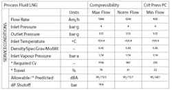
Q: I’m an instrumentation and control engineer at Egyptian Liqufied Natural Gas (ELNG), and I’d like to ask for your help in understanding the data sheets (below) I must use to purchase a control valve.
I’m particularly interested in learning more about FL and XT.
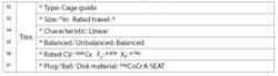
In another field on the data sheet, I have the below statement about CV.
Shaban Saad, Egyptian Liqufied Natural Gas / [email protected]
A1: As flowing liquid or gas approaches a control valve, the restriction causes it to accelerate. Acceleration requires energy, which must come from a drop in the static pressure upstream of the valve (P1 in Figure 1). This pressure drops as the area available for the flow decreases until the most constrictive location is reached. This location is called the vena contracta, and the pressure at that point is noted as Pvc. After this minimum constriction, the area available to the flowing stream increases, and some of the kinetic pressure converts back into static pressure. The pressure then rises until it reaches P2 at the outlet pressure.
The difference P1-P2 is caused by friction, and is called the permanent pressure drop. The pressure difference P2-Pvc is called the amount of pressure recovery. In valves with high recovery (rotary and gate valves), the kinetic effect is greater than the friction. If the flowing material is viscous, the opposite is the case, and the pressure recovery factor (FL) is low. Figure 1 also shows the effects of the inlet reducer and the outlet increaser effects.
![Figure 1: A pressure profile through a control valve where Pvc is the vena contracta pressure. The pressure revovery factor is calculated as FL = [(P'1-P2)/(P1-Pvc)]1/2](https://img.controlglobal.com/files/base/ebm/controlglobal/image/2024/04/6610071d30dab4001e9b600a-figure_1.png?auto=format,compress&fit=max&q=45?w=250&width=250)
FL is provided by the manufacturer and is based on the nature of the restriction the valve represents. It relates inversely to the pressure recovery—the higher it is, the lower the pressure recovery.
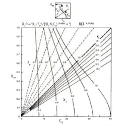
The XT and XTP factors in Figure 2 are provided by the valve manufacturers. The XT factor (critical pressure drop) describes how close the compressible flow is from choking (its velocity reaching sonic velocity), which occurs when P1/PVC exceeds 2.0. The choked flow also depends on piping geometry and the thermodynamic properties of the fluid. Even if the valves are tested, they’re seldom tested on a gas with the same thermodynamic properties as the process fluid. If the valve is installed between reducers or other fittings (as your 21-in. valve probably is), the XT factor becomes the combined factor XTP that has to be established by testing. Figure 2 can also be used to determine XTP it, where Cd = Cv/d2.
In connection with control valve sizing, there are a number of additional factors. They include:
- FF: Liquid Critical Pressure ration Factor
- FP and FLP: Piping Geometry Factors
- FR: Reynolds Number Factor
- Y: Gas Expansion Factors
- FK: Specific Heats Factor
- Z: Compressibility Factorű
Naturally, the sophisticated sizing method described in my handbook will give you accurate results only if the data provided and the algorithm used for the calculations are both good. This is not necessarily the case. Actually, in some cases, the user doesn’t even know what factors are considered in the sizing and how accurate they are.
Béla Lipták / [email protected]
A2: FL is a dimensionless factor that indicates the pressure recovery downstream of the valve. It will range between 0 and 1. The higher FL means pressure recovery is lower. The FL L will be determined by the manufacturer based on valve size, shape, flow rate and fluid properties. However, higher FL also indicates there is greater risk of cavitation.
XT is also a dimensionless factor that affects the pressure recovery based on valve design. A globe valve has a smoother flow transition than a butterfly valve. If you have a smaller XT, then downstream pipe length before next flow obstruction must be longer.
Raj Sreenevasan, principal control systems engineer / [email protected]
About the Author

Béla Lipták
Columnist and Control Consultant
Béla Lipták is an automation and safety consultant and editor of the Instrument and Automation Engineers’ Handbook (IAEH).
