This column is moderated by Béla Lipták, who also edits the Instrument and Automation Engineers’ Handbook, 5th edition, and authored the recently published textbook, Controlling the Future, which focuses on controlling of AI and climate processes. If you have a question about measurement, control, optimization or automation, please send it to [email protected]. When you send a question, please include your full name, job title and company or organization affiliation.
Q: As an instrumentation engineer, I’ve worked in factories and encountered large control valves that were oversized by my predecessors, requiring installation of a smaller valve in parallel. The valve-sizing software available today is powerful, and the results are correct in many cases. However, I find the best approach is to do preliminary sizing using online software, and then ask the valve manufacturer to check and confirm the correct sizing before ordering. If the supplied valve is the wrong size, the responsibility (and associated cost) is on the supplier to correct the mistake and supply the correct valve.
By doing this, I save the replacement costs, and learn what mistakes or omissions occurred in the original sizing data used in the software-based sizing, so we can avoid repetition in the future. What are the best ways to ensure using reliable sizing information?
Charles Palmer, process control consultant / [email protected]
A1: The more people review the sizing data provided for an application, the better the outcome is likely to be. I’ll focus on more than just the importance of using reliable and complete information, or the fact that data for sizing is often in error or reflects only normal operating conditions. I’ll describe some of the other important considerations in the process of valve sizing and selection.
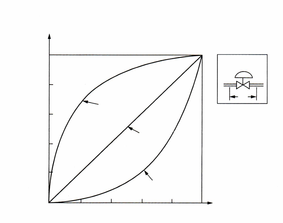
Usually, the first step is determining the required valve characteristics, which describe the relationship between flow through the valve and the value of the control signal received by the valve actuator. This relationship, if the actuator is linear (meaning that the valve Cv is proportional to the control signal), determines the valve gain—if the valve pressure drop (ΔP) is constant. The most common valve characteristics are linear, equal percentages, and quick opening (Figure 1).
The goal of picking the right valve characteristics is to keep the total loop gain constant. This total gain is the product of four gains, which are the process gain (Gp = %spam/%flow), sensor gain (Gs = %meas./%span), controller gain (Gc =%meas./%error), and valve gain (Gv = %flow/%lift). If tuned for quarter-amplitude damping, the controller gain is about 0.5, while the process gain varies as a function of the variable being controlled.
As shown in Figure 1, in a linear valve, its travel is linearly proportional with flow capacity, so the valve gain (Gv) is 1.0. In an equal percentage valve, a unit change in lift results in a flow change that’s a constant percentage of the flow occurring at that lift. Because valve gain rises as flow increases, these valve characteristics are selected for processes with the opposite gain characteristics (Gp drops when flow rises). Quick opening valves (plug valves) have the opposite characteristics; their gain rises with flow.
To specify the correct valve characteristics for a particular application, I consider the ratio of the pressure drop ratios in such a way that if the maximum pressure drop is less than twice the minimum, I use linear valves for flow, level and pressure control (except for the control of vapor pressure or liquid pressure, where equal percentage is the best choice). For heat transfer controls—the case in most temperature control loops—equal percentage valves are also recommended, which compensates for the drop in process gain as the load rises, while its own gain increases as the load rises. For square root-type flow loops, my recommendation is quick opening. If the maximum pressure drop is more than twice the minimum, I use linear valves for orifice flow and equal percentage for all others.
The above approach to pairing controlled variable and valve characteristics is correct, if the process fluid isn’t flashing, cavitating or approaching sonic velocity (choked flow). If it does, the selection becomes more complex, and the reader should refer to my handbook for details.
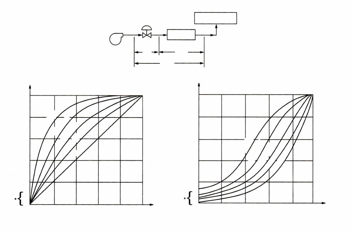
If on top of elevation, the pump must overcome pipe friction, so the Dc drops and the valve rangeability does, too. For example, at a Dc of 0.1, an equal percentage valve becomes linear, and its rangeability can drop from 50 to 10.
For this reason, and to keep the valve characteristics constant, I often recommend switching constant speed pumps to variable speed.
Béla Lipták / [email protected]
A2: I agree with Charles’ comments because generic, valve-sizing software may be good for training/instructional purposes and will probably give reasonably good results, but the models it uses might not exactly match the valve attributes of a particular vendor. There are also diverse auxiliary issues that would be involved with valve and assembly selection. These details would include chatter in near-closed conditions and rangeability if there’s an equal percentage-type trim, choked flow or cavitation. Associated auxiliary choices include actuator size, expander-contractor in the assembly, dual trims, etc.
R. Russell Rhinehart, emeritus professor, Oklahoma State University / [email protected]
About the Author
Béla Lipták
Columnist and Control Consultant
Béla Lipták is an automation and safety consultant and editor of the Instrument and Automation Engineers’ Handbook (IAEH).


